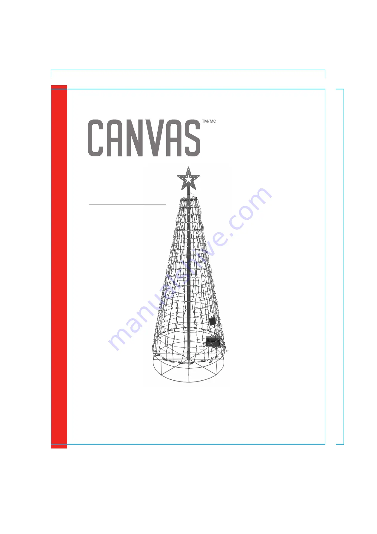
background image

PIXEL TREE

PRODUCT NO. 000-0000-0

MODEL N0. 151-3568

ASSEMBLY INSTRUCTIONS 

Toll-free: 1-888-670-6684

IMPORTANT: Please read this manual carefully before beginning assembly of this product.  
Keep this manual for future reference.

8.5”

11”

REMOTE MODEL N0. PIXEL-NM

Summary of Contents for 151-3568

Page 1: ...0000 0 MODEL N0 151 3568 ASSEMBLY INSTRUCTIONS Toll free 1 888 670 6684 IMPORTANT Please read this manual carefully before beginning assembly of this product Keep this manual for future reference 8 5 11 REMOTE MODEL N0 PIXEL NM ...

Page 2: ...eat Do not secure the wiring of the product with staples or nails or place on sharp hooks or nails Do not let LEDs rest on the supply cord or on any wire Unplug the product when leaving the house when retiring for the night or if left unattended This is an electrical product not a toy To avoid risk of fire burns personal injury and electric shock it should not be played with or placed where small ...

Page 3: ...are twisted until completely secured such that the ring can no longer be turned and the two portions of the connector are completely assembled Do not use a dimmer switch or install any additional Christmas lighting or ornamentation that is powered by a light bulb socket Doing this may result in damage to your light string or cause personal injury This action will result in a void of the limited wa...

Page 4: ...Tree base 1 1 Collapsible lighted tree frame with 5 pre programmed songs control box and a power box 1 2 Lighted star frame 1 3 Support pole 2 4 4 Lawn stake 4 5 Remote control 1 6 PART LIST ...

Page 5: ...tain carton for storage Determine the final display location before assembling the tree The Tree must be placed on level ground Place the tree base 1 in the desired location Step 2 Requires 1 2 Center and then place the lighted tree frame 2 over the top of the tree base 1 Be sure that the light string cord is not under the tree base 1 1 2 ...

Page 6: ...s 1 4 Insert the bottom pole section 4 tapered end up into the tree base 1 as illustrated 4 4 4 1 2 1 1 4 Requires 1 2 4 Align the top pole 4 tapered end up toward the center of the tree frame 2 next to the bottom pole 4 Step 4 ...

Page 7: ...rom the tree top point and place over the top pole 4 Insert the top pole 4 into the pole cap located on the inside top of the tree frame 2 Step 6 Requires 1 2 4 Proceed in lifting the tree frame 2 and place the top pole 4 on top of the bottom pole 4 which is already secured in the tree base 1 2 2 4 4 4 2 4 ...

Page 8: ...de elevation enabling accessibility to the control box and power box 2 due to the potential of a snowfall Proceed in mounting the 5 pre programmed songs control box 2 onto the tree base 1 into the two eyelets provided Step 7 Requires 1 2 The tree base 1 has spring hooks located on the outer edge of the tree base 1 Connect each spring hook to the corresponding chain on the tree frame 2 Check to mak...

Page 9: ...hook chain link from the base apply pressure to the top and bottom of the frame at the section where the twist is located Move link back into place and then release the frame Re hook chain link to the base 9 PRODUCT NO 000 0000 0 MODEL NO 151 3568 ASSEMBLY ...

Page 10: ...10 ASSEMBLY Step 9 Requires 2 4 Mounting the speaker box to the tree frame 2 as shown Step 10 Requires 3 Place the star 3 to the top of the tree 2 2 3 ...

Page 11: ...minate fully insert the plug into a working GFCI outlet or an outdoor rated extension cord Step 11 Step 12 Requires 1 5 Push or gently hammer support stakes 5 into the ground securing the tree base 1 Angle each stake 45 degrees toward the center of the tree 5 1 ...

Page 12: ...e department through one of the methods listed below A trained representative will assist you in troubleshooting the issue you are currently encountering If we determine that a light strand needs to be replaced one will be shipped to you Leave assembled if storage room permits or disassemble placing all components in the original carton Store in cool dry location away from sunlight REMOTE CONTROL ...

Page 13: ...changes or modifications not expressly approved by the party responsiblefor compliance could void the user s authority to operate the equipment which the receiver is connected for a Class B digital device pursuant to part 15 of the FCC Rules These the following two conditions 1 This device may not cause harmful interference and 2 this device must accept any interference received including interfer...

Reviews: