


24
Chapter 5
Chapter 5 Ports and Connectors
I/O Connectors
Serial ATA Connector
Serial ATA Power Connector
LAN 2
LAN 1
3
DDR3L
DDR3L
DDR3L
DDR3L
Mini PCIe with SIM
COM 4
RS232/RS422/RS485
12
10
3
1
JP22
1
1
1
(JP20)
(JP18)
(JP17)
(JP21)
1
3
12
10
COM 2
RS232/RS422/RS485
COM 1
RS232/RS422/RS485
USB 0
USB 3.0
HDMI
Reset
Power
39
40
2
1
LVDS LCD
Panel
USB 7
USB 6
Mic-in
1
Battery
Buzzer
1
Chassis
Intrusion
1
Clear CMOS
Data (JP24)
SPI
Flash
BIOS
eMMC
(optional)
iTE
IT8528E
Mini PCIe with LPC
mSATA
MicroSD
(optional)
1
System Fan
1
USB 0
Power
Select
(JP5)
1
2
5
6
(JP23)
1
1
1
(JP3)
(JP4)
1
2
10
9
COM 6
1
10
9
COM 5
1
1
USB 2 Power
Select (JP6)
USB 5-7 Power
Select (JP7)
1
2
10
9
USB 5
(JP25)
USB 2.0
USB 2.0
(JP17)
(JP20)
COM 4/DIO Select
(JP22, JP21)
Digital I/O 0-3 Output State
Digital I/O Power Select
Panel Power Select
(JP3)
(JP4)
(JP23)
Backlight Enable Power Select
Auto Power-on Select
(JP25)
Dimming Mode Select
(JP18)
Digital I/O 4-7 Output State
1
COM 3
RS232/RS422/RS485
4
1
(JP2)
(JP2)
LCD/Inverter Power Select
SATA 1
4
1 SATA
Power
1
SATA 2.0
I C
Line-out
DC-in
USB 2
USB 2
USB 2
USB 2
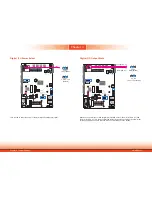
• 1 Serial ATA 2.0 port with data transfer rate up to 3Gb/s
• Integrated Advanced Host Controller Interface (AHCI) controller
The Serial ATA connector is used to connect the Serial ATA device. Connect one end of the Se-
rial ATA data cable to the SATA connector and the other end to your SATA device.
The SATA power connector supplies power to the SATA drive. Connect one end of the provided
power cable to the SATA power connector and the other end to your SATA device.
BIOS Setting
Configure the Serial ATA drives in the Advanced menu (“SATA Configuration” submenu) of the
BIOS. Refer to Chapter 7 for more information.
Features
7
RXN GND
TXP
TXN
GND
1
RXP
GND
SATA 1
SATA Power
SATA 2.0
+12V
+5V Gr
ound
1
Gr
ound
4
Audio Output
This Line-out jack is used to connect a headphone or external speakers. And the MIC-in con-
nector is used to connect an external microphone. The audio ports are built based on the
Realtek ALC888 chipset.
Driver Installation
Install the audio drivers. Refer to Chapter 8 for more information.
LAN 2
LAN 1
3
DDR3L
DDR3L
DDR3L
DDR3L
Mini PCIe with SIM
COM 4
RS232/RS422/RS485
12
10
3
1
JP22
1
1
1
(JP20)
(JP18)
(JP17)
(JP21)
1
3
12
10
COM 2
RS232/RS422/RS485
COM 1
RS232/RS422/RS485
USB 0
USB 3.0
HDMI
Reset
Power
39
40
2
1
LVDS LCD
Panel
USB 7
USB 6
Mic-in
1
Battery
Buzzer
1
Chassis
Intrusion
1
Clear CMOS
Data (JP24)
SPI
Flash
BIOS
eMMC
(optional)
iTE
IT8528E
Mini PCIe with LPC
mSATA
MicroSD
(optional)
1
System Fan
1
USB 0
Power
Select
(JP5)
1
2
5
6
(JP23)
1
1
1
(JP3)
(JP4)
1
2
10
9
COM 6
1
10
9
COM 5
1
1
USB 2 Power
Select (JP6)
USB 5-7 Power
Select (JP7)
1
2
10
9
USB 5
(JP25)
USB 2.0
USB 2.0
(JP17)
(JP20)
COM 4/DIO Select
(JP22, JP21)
Digital I/O 0-3 Output State
Digital I/O Power Select
Panel Power Select
(JP3)
(JP4)
(JP23)
Backlight Enable Power Select
Auto Power-on Select
(JP25)
Dimming Mode Select
(JP18)
Digital I/O 4-7 Output State
1
COM 3
RS232/RS422/RS485
4
1
(JP2)
(JP2)
LCD/Inverter Power Select
SATA 1
4
1 SATA
Power
1
SATA 2.0
I C
Line-out
DC-in
USB 2
USB 2
USB 2
USB 2
Line-out
Mic-in
1
4
Gr
ound
MIC2-RI
MIC2-LI
MIC2-
JD


