


31
2
Hardware Installation
COM 1
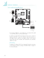
2.5.2 Serial Port
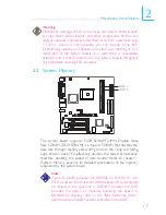
The system board is equipped with an onboard serial port (Teal/
Turquoise) at location CN4 for COM 1. It is also equipped with an
optional 9-pin connector at location J6 for COM 2.
To connect COM 2, please refer to the following description. The
serial port may be mounted on a card-edge bracket. Install the card-
edge bracket to the system chassis then insert the cable connector
to J6. Make sure the colored stripe on the ribbon cable is aligned
with pin 1 of J6.
The serial ports are RS-232C asynchronous communication ports
with 16C550A-compatible UARTs that can be used with a modem,
serial printer, remote display terminal or other serial devices.
BIOS Setting
Select the serial ports’ I/O address in the Integrated Peripherals
submenu (“Super IO Device” section) of the BIOS. Refer to chapter
3 for more information.
W
W
1
9
2
CD
TD
RD
DTR
SG
RTS
DSR
CTS
RI
COM 2
(optional)