


www.dfi.com
21
Chapter 5 Ports and Connectors
Chapter 5
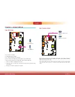
USB Ports
The USB device allows data exchange between your computer and a wide range of simultane-
ously accessible external Plug and Play peripherals.
The system board is equipped with four onboard USB 3.0 ports (USB 1-2/USB 3-4). The 10-pin
connector allows you to connect 2 additional USB 2.0 ports (USB 4-5). The additional USB port
may be mounted on a card-edge bracket. Install the card-edge bracket to an available slot at
the rear of the system chassis and then insert the USB port cables to a connector.
BIOS Setting
Configure the onboard USB in the Advanced menu (“USB Configuration” submenu) of the
BIOS. Refer to chapter 7 for more information.
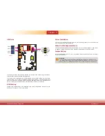
USB 2.0
1
2
10
9
VCC
-Data
+Data
GND
Key
VCC
-Data
+Data
GND
N.C.
Important:
If you are using the Wake-On-USB Keyboard/Mouse function for 2 USB ports, the
+5V_standby power source of your power supply must support ≥1.5A. For 3 or more
USB ports, the +5V_standby power source of your power supply must support ≥2A.
Driver Installation
You may need to install the proper drivers in your operating system to use the USB device.
Refer to chapter 8 for more information.
Wake-On-USB Keyboard/Mouse
The Wake-On-USB Keyboard/Mouse function allows you to use a USB keyboard or USB mouse
to wake up a system from the S3 (STR - Suspend To RAM) state. To use this function:
Jumper Setting
JP23 and JP26 must be set to “1-2 On: +5V_standby”. Refer to “USB Power Select” in chapter
4 for more information.
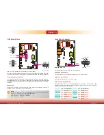
USB 4-5
USB 2
USB 3.0
USB 1
USB 4
USB 3


