8514-238-001 REV PR page 4
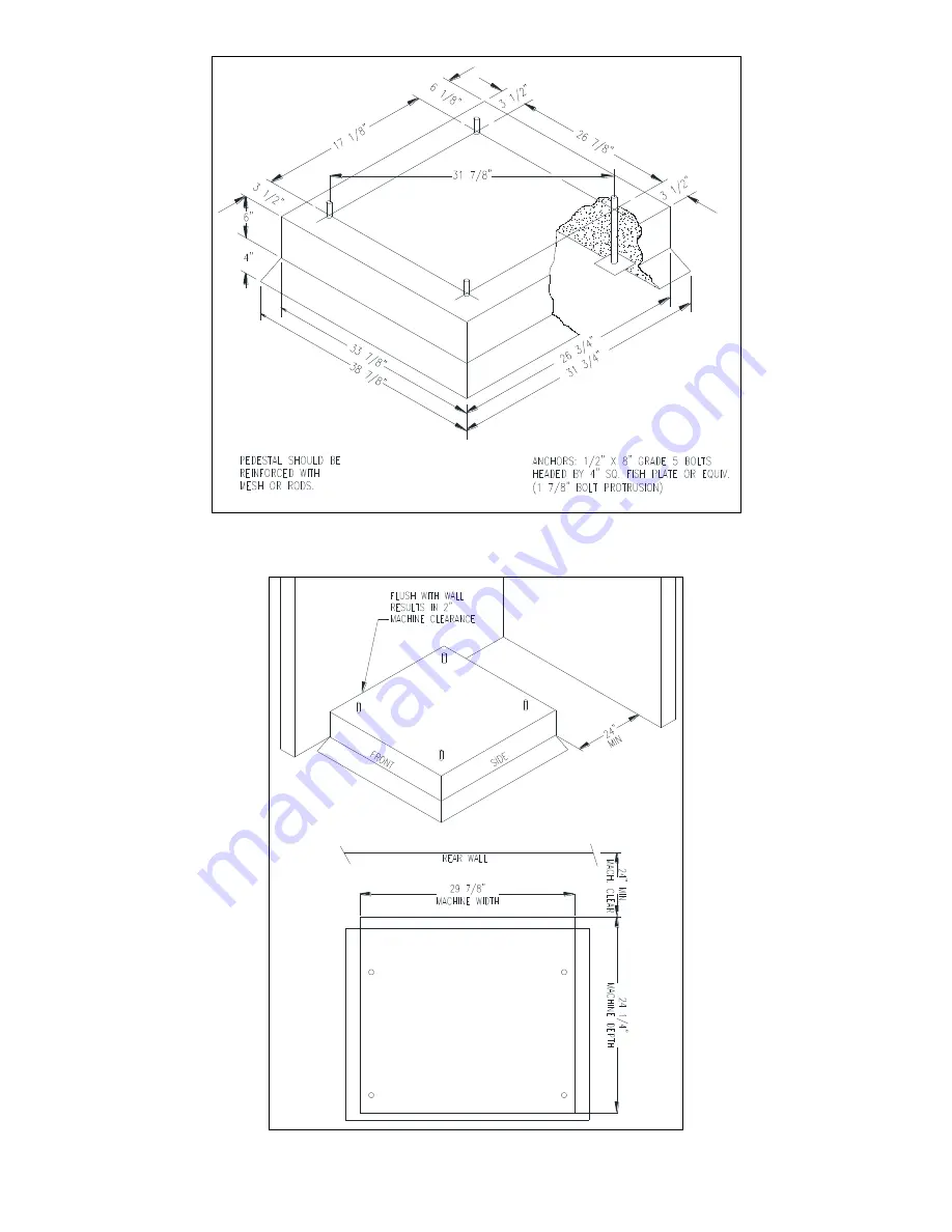
Figure 1-1: Concrete Pedestal Mounting
Figure 1-2: Floor Outline
Page 1: ...r flammable substances in or near this washer Keep all panels in place They protect against shock and injury and add rigidity to the washer PREVENTIVE MAINTENANCE REQUIREMENTS DAILY Check that the loa...
Page 2: ...ENCY DRIVE INDICATORS 12 3 MACHINE PROGRAMMING INSTRUCTIONS 13 3 1 EDITING AN EXISTING CYCLE 13 3 2 DEFAULT WASHER CYCLE PROGRAMS 15 3 3 RAPID ADVANCE MODE 19 4 WASHER ERROR CODES 20 5 TROUBLESHOOTING...
Page 3: ...ansion anchors must be of a quality grade and a minimum of 1 2 inch 14 mm diameter Mounting hardware is not provided with the machine 1 2 MOUNTING A concrete pedestal or steel mounting base that eleva...
Page 4: ...8514 238 001 REV PR page 4 Figure 1 1 Concrete Pedestal Mounting Figure 1 2 Floor Outline...
Page 5: ...8514 238 001 REV PR page 5 Figure 1 3 Machine Mounting Detail...
Page 6: ...8514 238 001 REV PR page 6 Figure 1 4 T 400 Industrial Washer Mounting Diagram...
Page 7: ...e 208 240VAC 60 Hz washing machines are intended to be permanently installed appliances No power cord is provided The machine should be connected to an individual branch circuit not shared by lighting...
Page 8: ...rmer is located inside the control trough and steps a range of 208 to 240 volts down to 115 volts There are two terminals on the controls transformer for the primary incoming power Use the terminal ma...
Page 9: ...Drive VFD and Table 2 for appropriate jumper connection points indicated with an X for the desired maximum spin speed setting If no adjustment to default spin speed is desired do not remove or add an...
Page 10: ...and Circuit Identification Chemical Injection hoses are to be inserted into the injection inlet at the upper right rear of the washer These hoses should be inserted into the round PVC pipe a minimum o...
Page 11: ...iate cycle number 1 through 6 for the type of load being washed See the default cycle descriptions in section 3 2 Use the UP and DOWN keys to change the two digit cycle number on the display to the de...
Page 12: ...is interrupted during the cycle 2 4 VARIABLE FREQUENCY DRIVE INDICATORS There are three small red LEDs located on the upper Variable Frequency Drive VFD cover They are labeled as READY RUN and FAULT a...
Page 13: ...power to the washer Washer must be in idle mode to program 3 1 2 Ensure washer is in PROGRAM mode Locate the RUN PROGRAM key switch and key The current mode is indicated by the alignment of the key s...
Page 14: ...2 3 and 4 If the time is set to 00 then the bath will be eliminated from the cycle 01 to 15 minutes for Final Rinse Water Temperature t_ HH for hot water CH for warm water CC for cold water EE for no...
Page 15: ...nce Blank cycle tables have been provided at the end of section 3 2 NOTE The Wash Cycle programming mode will automatically exit and return to the Idle mode if no buttons are pressed for one minute 3...
Page 16: ...h Care Bath Bath Cycle Time min Water Temp Water Level Delay Fill Spin Time min Injection Source Flush 3 CH HI d Prewash 2 CH HI d Wash 7 HH LO d 1 Detergent Rinse 1 1 HH HI d Rinse 2 7 HH LO d 2 Blea...
Page 17: ...Bath Bath Cycle Time min Water Temp Water Level Delay Fill Spin Time min Injection Source Flush 3 CH HI d Prewash 2 CH HI d Wash 2 CH HI d Rinse 1 7 HH LO d 1 Detergent Rinse 2 2 HH HI d Rinse 3 7 HH...
Page 18: ...al Rinse Cycle _____ Description _________________________________ Bath Bath Cycle Time min Water Temp Water Level Delay Fill Spin Time min Injection Source Flush Prewash Wash Rinse 1 Rinse 2 Rinse 3...
Page 19: ...ot yet started press the START button To rapid advance to the next step in the wash cycle push both the UP and START buttons at the same time The display will show Ad advance in the display The washer...
Page 20: ...power to the washer Replace the pressure switch Turn on power to the washer See Note 6 Wrong washer size for drive type Turn off the power to the washer Check to ensure all the harnesses are properly...
Page 21: ...the drive to cool Check the cooling fins of the drive to ensure proper airflow Check the wiring to the drive including the fan wiring If no problem is observed turn on power to the washer and test Se...
Page 22: ...ect replace transformer Check PCB board Check all wire connections for sure contacts Check wiring between PCB Check data cable phone type connectors unplug and VFD and replug with power removed Check...
Page 23: ...ain relay PCB Check black or white wires at Molex plug on PCB at main controller and at relay PCB Pressure Switch Check pressure switch continuity between terminal contacts If no continuity check pres...
Page 24: ...witch for continuity across terminals 21 22 indicating pressure switch has reset to the empty position If no continuity change pressure switch Machine starts and does not operate VFD Check yellow enab...
Page 25: ...day basis These smaller surges can shorten overall life of electrical components of all types and cause their failure at a later date Although they can t protect against all events these protective de...
Page 26: ...ainer Inlet Hose 4 Contact distributor or Dexter Laundry Inc if a steel mounting base is required For service and parts information contact your local Dexter agent To find your local Dexter agent use...