


Installing Drive Pulley
Step 1:
Install hub on cylinder shaft.
Step 2:
Hold hub against rear bearing with 5/8” bolt and flat washer in end of cylinder shaft.
Step 3:
Line up 3 unthreaded holes in pulley with the 3 threaded holes in tub.
Step 4:
Insert 3 pulley bolts and tighten evenly alternating bolts to 30ft/lb. Note: Overtightening or uneven
tightening can break drive pulley.
Water Seals Replacement
A.
Remove cylinder from washer (see Cylinder (basket) removal).
B.
Remove water seals from the seal mounting plate on the cylinder shaft with your fingers.
C.
The primary and secondary seals that mount on the sealing ring may.be slid over the shaft and seated
on the metal sealing ring with your fingers. In the unlikely event that the metal ring that mounts these
sealing rings were to be damaged or moved, a new one would need to be pressed on. The T-900 ring
must be pushed against the stop on the shaft. After installing the seals, lubricate the faces of the seals
with silicone grease.
D.
Install cylinder as previously outlined.
Bearing Housing Assembly Removal
A.
Remove cylinder from washer (see Cylinder (basket) removal).
B.
Remove 6 7/16” tub back to bearing housing cap screws.
C.
Remove 6 3/4” bearing housing to frame bolts.
D.
Remove bearing housing from frame.
E.
Remove the retaining ring next to the front bearing.
F.
The bearings are pressed into the housing and must be pressed back out.
Bearing Housing Assembly Reassembly
A.
When installing new bearings into a bearing housing, first press the front (large) bearing into the
housing until it bottoms and install the snap ring. With the bearing spacer in place, press the rear
bearing in until the spacer is snug between the two bearings. Note: If the tub-back water-seal mating
ring has been moved it must be cleaned and resealed with silastic around all 6 bolt holes and around
the outer edge.
B.
Set bearing housing on frame.
C.
Install and torque 6 tub back to bearing housing cap screws according to the previous chart.
D.
Install and torque 6 bearing housing to frame bolts according to the previous chart.
E.
Install cylinder as previously outlined.
Drive Motor Removal
Step 1:
Remove the drive belt as explained in previous instructions.
Step 2:
Remove the tension spring and bracket.
Step 3:
Disconnect the motor wires at the variable frequency drive unit.
Step 4:
Loosen the set screws on the motor support shaft.
Step 5:
Remove the retaining bolt from the front of the support shaft.
Step 6:
Remove the motor support shaft.
Step 7:
Lift motor out of machine. Note: On larger washers it is advisable to put a board under the motor
and slide it out rather than lifting it.
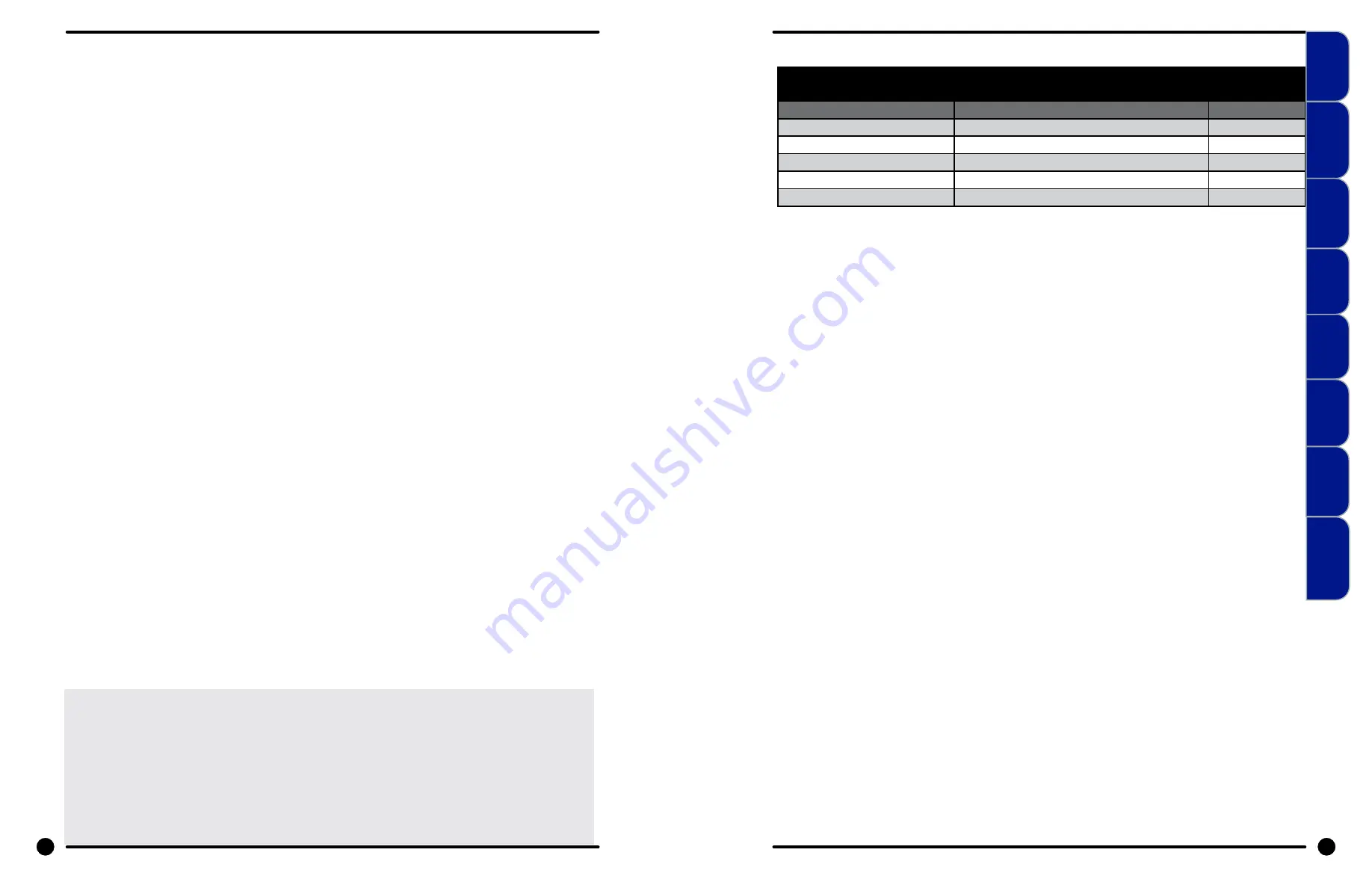
T-900 Bolt Torque Chart
Bolt Size
Where Used
Torque
7/16" Stainless Cap Screw
Outer Tub to Bearing Housing
60-80 ft/lbs
3/4" Bolt
Bearing Housing to frame
200-300 ft/lbs
1/2" Bolt
Outer Tub Clamping Band to Frame
70-110 ft/lbs
1/2" Bolt
Outer Tub Clamping Band - Top
30-40 ft/lbs
3/8" Cap Screw
Drive Pulley to Hub
30 ft/lbs
44
45
Part # 8533-031-001 6/22
Part # 8533-031-001 6/22
Machine
Mounting
Installation
& Operation
Trouble-
shooting
Machine
Service
Electrical
Wiring
Parts
Data
Coin
Handling
Maintenance


