90
Key Description
T-120
QTY
*
Door Assy-Upper, OPL (Wht)
9960-328-004
1
*
Screw-Phillips, 10Bx1 3/4
9545-008-014
4
*
Washer-Finish
8641-585-001
4
*
Nut-Spring
8640-399-001
4
5
Box-Control Front, Black
9041-107-002
1
6
Screw-10ABx3/8
9545-008-024
4
*
Screw-10-32 x 1/2, Chrome
9545-012-003
2
8
Plate Assembly-Meter, Black
9982-394-002
1
9
Nut-Elastic Stop, #10-32
8640-413-004
2
11
Display Control
9857-230-002
1
12
Nut, #6-32
8640-411-003
3
14
Nut, #6-32
8641-411-003
1
15
Screw, #10-32 x1/2 Green
9545-008-027
1
16
Lock Washer #10
8641-582-006
1
19
Screw Torx-6BSD x 1/2, BLK, “T10”
9545-031-009
2
*
Harness-Display Control
9627-922-001
1
*
Harness-Temp Probe
9627-917-002
1
22
Plug-2”
9456-041-009
1
23
PCB Assy. Main Control
9799-027-001
1
24
Plate Assy. - Control Board
9982-395-001
1
25
PCB Assy. - Control Board (Only)
9474-003-001
1
26
Screw - panhdcr, #6-32 x 1/2 (SS)
9545-044-010
6
27
Lockwasher - exttooth, #6
8641-582-005
6
Dryer Cabinet Group Continued
Part # 8533-125-001 7/21
Summary of Contents for DN0120
Page 10: ...10 Part 8533 125 001 7 21 Notes ...
Page 11: ...11 Part 8533 125 001 7 21 Section 1 Dryer Specifications and Mounting ...
Page 13: ...13 Machine Dimensions Front View Part 8533 125 001 7 21 ...
Page 14: ...14 Machine Dimensions 120Lb Part 8533 125 001 7 21 ...
Page 15: ...15 Machine Dimensions 120Lb Part 8533 125 001 7 21 ...
Page 16: ...16 Part 8533 125 001 7 21 Notes ...
Page 17: ...17 Part 8533 125 001 7 21 Section 2 Dryer Installation ...
Page 23: ...23 Part 8533 125 001 7 21 Notes ...
Page 24: ...24 Part 8533 125 001 7 21 Notes ...
Page 25: ...25 Part 8533 125 001 7 21 Section 3 Dryer Operating Programing Instructions ...
Page 43: ...43 Part 8533 125 001 7 21 Notes ...
Page 44: ...44 Part 8533 125 001 7 21 Notes ...
Page 45: ...45 Part 8533 125 001 7 21 Section 4 Service Procedures Trouble Shooting and Schematics ...
Page 69: ...69 Part 8533 125 001 7 21 Notes ...
Page 82: ...82 Wiring Schematic 11 Part 8533 125 001 7 21 ...
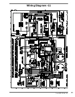
Page 83: ...83 Wiring Diagram 11 Part 8533 125 001 7 21 ...
Page 84: ...84 Wiring Schematic 10 Part 8533 125 001 7 21 ...
Page 85: ...85 Wiring Diagram 10 Part 8533 125 001 7 21 ...
Page 86: ...86 Part 8533 125 001 7 21 Notes ...
Page 87: ...87 DN0120NE 11EO1_ DN0120NE 10EO1_ Part 8533 125 001 7 21 Section 5 Dryer Parts Data ...
Page 89: ...89 3 1 2 10 12 14 15 18 7 8 9 19 21 16 5 6 4 13 11 16 14 15 Part 8533 125 001 7 21 ...
Page 91: ...91 12 14 17 19 20 23 5 6 15 16 9 22 13 11 8 5 24 25 26 27 Part 8533 125 001 7 21 ...
Page 93: ...93 1 1 2 4 3 Part 8533 125 001 7 21 ...
Page 95: ...95 3 1 2 10 12 7 5 6 4 9 11 8 6 19 Part 8533 125 001 7 21 ...
Page 101: ...101 3 1 2 10 12 14 7 5 6 4 9 13 11 8 Part 8533 125 001 7 21 ...
Page 107: ...107 Part 8533 125 001 7 21 Notes ...
Page 108: ...108 3 1 2 12 13 14 17 20 16 23 5 4 15 9 10 24 27 11 25 32 31 30 33 Part 8533 125 001 7 21 ...
Page 111: ...111 1 2 3 4 5 6 8 9 Part 8533 125 001 7 21 ...
Page 113: ...113 14 2 3 4 5 7 6 5 12 9 10 11 13 16 15 17 18 19 Part 8533 125 001 7 21 ...
Page 114: ...114 Part 8533 125 001 7 21 ...
Page 115: ...115 Part 8533 125 001 7 21 ...
Page 116: ...116 Wiring Schematic 11 Part 8533 125 001 7 21 ...
Page 117: ...117 Wiring Diagram 11 Part 8533 125 001 7 21 ...
Page 118: ...118 Wiring Schematic 10 Part 8533 125 001 7 21 ...
Page 119: ...119 Wiring Diagram 10 Part 8533 125 001 7 21 ...
Page 120: ...120 Part 8533 125 001 7 21 Notes ...
Page 121: ...121 DN0120NE 39AO1_ Part 8533 125 001 7 21 Section 6 50Hz Dryer Parts Data ...
Page 123: ...123 Part 8533 125 001 7 21 Notes ...
Page 124: ...124 Wiring Schematic 39 Part 8533 125 001 7 21 ...
Page 125: ...125 Wiring Diagram 39 Part 8533 125 001 7 21 ...
Page 126: ...126 Part 8533 125 001 7 21 Notes ...
Page 127: ...127 Part 8533 125 001 7 21 Section 7 Maintenance Schedule ...


