background image


NDS3228A  8  in  1  MPEG-2  H.264  SD 

Encoder  User’s  Manual 

                                                                                    32 / 55 

device mode as 1IP)


8IP: 

This mode refers to the 8 SPTS and outputs every single program with separate IP address. 

Users  need  to  enable  the  IP  Output 

  in  every  channel  interface  (refer  to 

4.3.1.3  System  Parameters).  (The  device  will  automatically  enable  IP  Outout  founction 

mentioned here if users change the device mode to 8IP)


When 1IP is set as the Device Mode, then the 8IP mode is non-effective. 


Output Port 

Users can set the 

output port 

by modifying the value in this field.


Original Network ID 

This 16-bit field gives the label identifying the network ID of the originating delivery system. 

The value ranges from 0 to 0xFFFF. 


Transport Stream ID 

This  is  a  16-bit  field  which  serves  as  a  label  for  identification  of  this  TS  from  any  other 

multiplex within the delivery system. The value ranges from 0 to 0xFFFF. 


Output Bit Rate (Mbps) 

This  includes  the  effective  bit-rate  of  encoding  channel  1-8,  the  effective  bit-rate  from  ASI 

input and the bit-rate of stuffed null packets. 


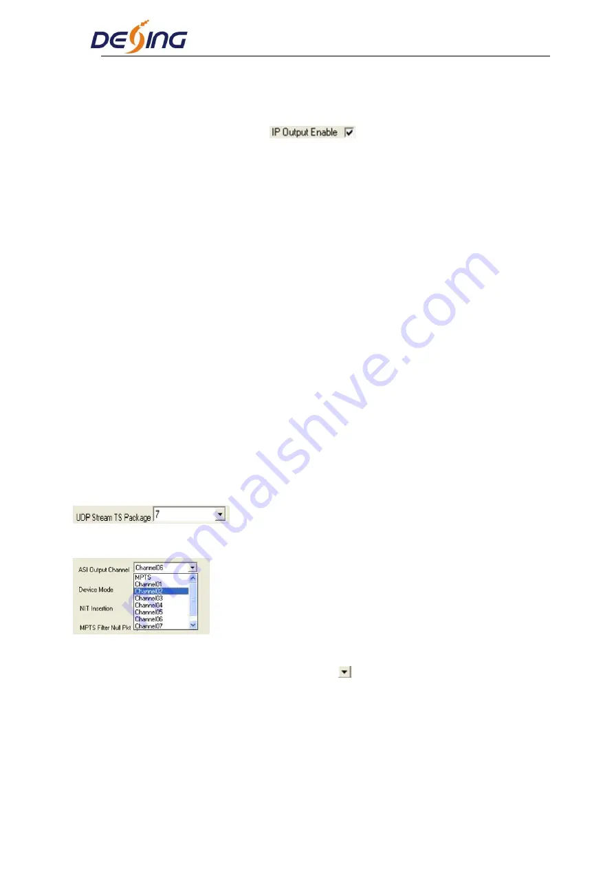
UDP Stream TS Package 

  Users can set the amount of TS packages here. 


ASI Output Channel 


This  device  supports  1  MPTS  (Multiple  Programs  Transport  Stream)  and  8  SPTS  (Single 

Programs  Transport  Stream)  output.  User  can  click 

  to  triger  a  pull-down  list  to  select  the 

output type


NIT Insertion 

In this field, users can decide whether to effect the NIT (Network Information Table) insertion 

function.   


SDT Insertion 

Summary of Contents for NDS3228A

Page 1: ...NDS3228A 8 in 1 MPEG2 H 264 SD Encoder User s Manual SW Version 2 14 HW version 0 3 Chengdu Dexin Digital Technology Co Ltd...

Page 2: ...on Preparation 5 2 3 Wire s Connection 7 2 4 Signal Cable Connection 7 Chapter 3 Operation 11 3 1 Initializing 11 3 2 General Setting 11 Chapter 4 NMS Operation Optional 24 4 1 Installation 24 4 2 Sof...

Page 3: ...an ASI input and can multiplex the input TS with the 8 encoded SPTS to generate a MPTS output 1 2 Main Features Support 8 AV CVBS or SDI optional 1 ASI Input H 264 and Mpeg2 video encoding MPEG1 Audi...

Page 4: ...tion Sharpening Audio Encoding MPEG1 Audio Layer 2 LC AAC HE AAC V2 Sampling rate 48KHz Bit rate 32Kb s 384Kb s each channel Multiplexing 1 ASI input multiplexed with local 8 channels of TS Stream out...

Page 5: ...area All indicators will light on when the device is on the current working state 1 LCD Screen 2 Indicators Power Indicator TS In Input Lock Indicator CH1 CH8 When the program has been multiplexed th...

Page 6: ...nels 5 ASI Input Port 6 2 ASI Output Ports 7 Data Port for IP Signal Output 8 NMS Network Management Port 9 Power Switch 10 Fuse 11 Power Socket 12 Grounding Pole Rear Panel Illustration SDI input 1 8...

Page 7: ...s install device please follow the below steps The details of installation will be described at the rest part of this chapter Users can also refer rear panel chart during the installation The main con...

Page 8: ...e alarm system and extinguisher Power Requiring device power air conditioning power and lighting power are independent to each other Device power requires AC power 220V 50Hz Please carefully check bef...

Page 9: ...ike this power switch is on the left power supply socket is on the right and the fuse is just between them Connecting Power Cord User can insert one end into power supply socket while insert the other...

Page 10: ...y find the CVBS input connector on the device according to the connector mark described on the rear panel illustration and then connect the analog CVBS video and unbalanced audio cables in the accesso...

Page 11: ...nnector mark described on the rear panel illustration and then connect the ASI cable in the accessories One end is connected to the encoder s ASI out connector ASI1 ASI2 while the other end to the TS...

Page 12: ...NMS interface on the device according to the connector mark described on the rear panel illustration and then connect the network CAT5 One end of the network cable is connected to the encoder s NMS co...

Page 13: ...eter or page up down when parameter is inactivated LOCK To Lock the screen cancel the lock state After pressing lock key the system will question the users to save present setting or not If not the LC...

Page 14: ...eo input parameters and select programs to multiplex The LCD will display 8 submenus which from Encoding Channel 1 to Encoding Channel 8 The setting principle is the same for Encoding Channel 1 8 so h...

Page 15: ...1 1 the operation interface will turn up as following page NOTE Below explanations are applied in this entire manual 1 When user enter 1 1 1 1 the LCD displays only one option which is the device s cu...

Page 16: ...nderline through LEFT RIGHT keys 3 To modify the value of underlined character through UP DOWN keys 1 1 1 2 Brightness 128 0 80 1 1 1 3 Contrast 128 0 80 1 1 1 4 Saturation 128 0 80 1 1 1 5 Hue 000 0...

Page 17: ...lue VBR Variable Bit rate means that the bit rate will always change along with the video scene changing Bit Rate Max Bit Rate Min Bit Rate User can modify the video encoding bit rate maximal and mini...

Page 18: ...the input audio sample rate Users can set relevant audio sample rate by moving UP DOWN keys After the setting users can press enter key again to take the modification into effect And the LCD will dis...

Page 19: ...nter this submenu The LCD will display as below Video Audio PMT PCR PID Settings Users can set these parameters by pressing ENTER to enter these submenus The LCD will display the following pages and t...

Page 20: ...interfaces Null Packet Users can choose YES filter the null packet or NO don t filter null packet to decide whether to filter the null packet or not Broadcast Yes to pass the audio only then no video...

Page 21: ...01 01 YES NO 3 2 2 ASI Setting Users can check the ASI input program amount in this interface and the LCD will display the following page Prog 006 represents the input program is 6 and Out 003 repres...

Page 22: ...n this interface After users press the ENTER key the operating interface will display the following page 3 2 IP Out Address 224 002 002 002 3 2 3 3 IP Out Port In this menu users can set the encoder I...

Page 23: ...3 8 UTC Time UTC refers to Universal Time Coordinated User can enter this menu to set the time as needed and it will then generate the TDT table and show in the user s STB 3 2 3 9 Null Packet 3 2 4 N...

Page 24: ...the MAC address is ffffffffffff users must modify the address through special software otherwise the IP output data will be filter out when the IP stream passes through the router 3 2 5 Saving Config...

Page 25: ...efault 3 2 7 Version Users can check the device software version and hardware version and the LCD will display the following interface when users press the ENTER key 3 2 8 Language User can select the...

Page 26: ...mple the version number of network management software 4 12E exe is 4 12 English version or place different versions of network management software to the same directory When the network management so...

Page 27: ...with database record automatically and the main interface will appear 4 2 2 Main Interface User can create a device node tree in the left column by adding modifying and deleting the device node This s...

Page 28: ...Edit pull down menu on the menu row The device will confirm the given frequency while user clicks OK User can also click right mouse key to pop up the short cut menu in device tree or in the left blan...

Page 29: ...t under Given Frequency Point User should choose the frequency point in advance and then the dialog box of Add Equipment will pop up when user clicks Add Equipment item in the Edit pull down menu on t...

Page 30: ...ult IP of NDS3228A Encoder is 192 168 2 136 also you can check its IP address in the front panel of device in case the IP changed unexpected 2 The PC IP address and device IP address should be in the...

Page 31: ...device s flash while user can also reload the saved parameters from device s flash and refresh the device s parameters setting according to the loaded values by clicking Alternatively user can also c...

Page 32: ...ill display the encoder interface in operating area The interface is mainly composed of encoding video parameters audio parameters and the encoding system parameters output parameters and etc 4 3 1 Pa...

Page 33: ...or not Users can modify the IP address here as well IP Out Address Service IP Address Service Mask Service Gateway Users can set the address by modifying the value in these four fields Device Mode Use...

Page 34: ...of the originating delivery system The value ranges from 0 to 0xFFFF Transport Stream ID This is a 16 bit field which serves as a label for identification of this TS from any other multiplex within th...

Page 35: ...ate Users can only modify the Max Video Bit Rate when the Bit rate mode is VBR while CBR mode is selected Max Video Bit Rate box turns gray and users can just check it Input channel selection area The...

Page 36: ...ing parameters 4 3 1 2 Audio Parameters 4 3 1 3 System Parameters Audio Gain User can set the value of Audio Gain by moving the slider or directly inputting the value in the right box The adjustment r...

Page 37: ...modifying the value in these two fields Original Network ID This 16 bit field gives the label identifying the network ID of the originating delivery system The value ranges from 0 to 0xFFFF Transport...

Page 38: ...can set the MCTF Motion Compensation Temporal Filtering Length Pre Deblocking Length and ACBAC function in this interface 4 3 2 Multiplexing The programs in the left column represent all input program...

Page 39: ...To refresh the outputting terminal and get the outputting information Multiplex the input programs to the output channels after selecting the target program with The system will automatically allot th...

Page 40: ...boxes of corresponding items and click CONFIRM to effect Refresh getting PID filter table from the device Setting submitting the PID filter table to the device Check All selecting all the selections...

Page 41: ...e multiplexing module without changing anything This is the main purpose of this function The display will show as below when user clicks Add button Input PID and Output PID The Old Input PID is the P...

Page 42: ...eters NIT Network Information Table NIT table is a very important table for describing the network and TS Users can set the parameters of the output NIT table The parameter describes the output TS s n...

Page 43: ...u is active And also the device will insert the EIT table into the output TS It means to replace the NIT table when users select it and then users can edit the NIT table and output it Users can add th...

Page 44: ...1 Difference between Set and Remote Save In many cases during the configuration of parameters in NMS users save the modified configuration by clicking Set in which way the configuration can only be s...

Page 45: ...ers input the new NMS IP Address for the device and click OK button to confirm Users can then note the indicator light turns red which signifies the equipment has disconnected Users then can refer to...

Page 46: ...te that the default user name is admin and no password User can add users and passwords as needed User clicking Setting in the menu bar and selecting User Setting in the pull down list the below dialo...

Page 47: ...NDS3228A 8 in 1 MPEG 2 H 264 SD Encoder User s Manual 45 55...

Page 48: ...136 We can modify the IP through the front panel Connect the PC Personal Computer and the device with net cable and use ping command to confirm they are on the same network segment I G the PC IP addre...

Page 49: ...hannel as Figure 3 The interface and setting principle of each channel are the same from Encoder 1 to Encoder 8 Here just take Encoder 1 as example User can click any item here to enter the correspond...

Page 50: ...in this interface Video Status Green light indicates the corresponding source cables are properly connected Encoding Status Green light indicates the encoding process is running normally which otherwi...

Page 51: ...we can output all the programs Similarly user can cancel the multiplexed programs from the right box to select all the input output programs with one time clicking Time limitation to parse the input p...

Page 52: ...etwork info for the output TS Figure 5 Device Mode User can click to triger a pull down list to select the device mode 1IP This mode refers to MPTS and outputs the programs which have been multiplexed...

Page 53: ...ically enable IP Outout founction mentioned here if users change the device mode to 8IP When 1IP is set as the Device Mode then the 8IP mode is non effective Save Restore From the menu on left side of...

Page 54: ...on as needed Figure 8 Password When user clicks Password it will display the password screen as Figure 9 Here user can change the Username and Password for login to the device Figure 9 Backup Load Cli...

Page 55: ...3228A 8 in 1 MPEG 2 H 264 SD Encoder User s Manual 53 55 and find the backup configuration file path After selecting the file click Load File to load the backup file to the device Figure 10 Browse But...

Page 56: ...e between 0 to 45 C Making sure good ventilation for the heat sink on the rear panel and other heat sink bores if necessary Checking the input AC within the power supply working range and the connecti...

Page 57: ...NDS3228A 8 in 1 MPEG 2 H 264 SD Encoder User s Manual 55 55 Chapter 7 Packing list NDS3228A 8 in 1 MPEG 2 H 264 SD Encoder 1pcs User s manual 1pcs CVBS SDI Cable 8 pcs ASI cable 1pcs Power cord 1pcs...

Reviews: