background image

9

Before connecting a 12 V DC mains 
adapter to the mains, make sure that the 
mains current is 230 V ~ 50 Hz and 
equipped with a max. 16 amp fuse in 
accordance with requirements.

•    This device does not serve as primary 

explosion protection as defi ned by the 
guidelines of the employer’s liability insur-
ance associations.

•    Do not cover the device with any object. 

This could diminish the performance of 
the sensor.

•    Make sure that the device does not come 

into contact with moisture. 

•   Protect the device from strong magnetic 

or electric fi elds.

•   Protect the device from heavy mechanical 

strain and shocks.

•   Only use the device with the supplied 

original parts or parts that are designed 
for it.

•   Check before initial operation that all 

components are assembled in accord-
ance with the operating instructions.

•   Before assembly and initial operation of 

the device, check that the delivery is 
complete and undamaged.

•   The device must only be repaired by 

authorized and skilled specialists. Failure 
to observe this instruction risks  damage 

resulting from improper use and loss of 
the warranty.

•    Position the device so that the sensors 

can detect escaping gas. 

•    Use the device at normal room tempera-

tures only. Higher or lower temperatures 
can diminish performance.

•    Do not open the device. Opening the 

device will lead to expiry of the warranty.

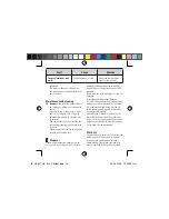
•    For connection in cars, caravans or on 

boats, fi t the (12 V DC) power supply 
cable with a switch approved for this pur-
pose. Switch the gas alarm off when the 
gas supply is switched off. This saves 
electricity, since the gas alarm otherwise 
constantly uses electricity. 

•    Connect the 12 V DC terminal screws 


either to the mains adapter supplied with 
the gas alarm or a 12 V DC power supply 
source in cars, caravans and boats. Dual 
connection (parallel connection) will dam-
age the mains adapter.

•    For connection to the 12 V DC battery, fi t 

the 12 V DC connecting cable with a fuse 
(250 mA). 

•    Remove the “IMPORTANT INFORMATION” 

page from the operating instructions and 
hang it on the wall in a visible position 
directly next to the gas alarm.

IB_GA607_UK_IRL_Content.indd   9

IB_GA607_UK_IRL_Content.indd   9

20.09.2005   13:59:53 Uhr

20.09.2005   13:59:53 Uhr

Summary of Contents for GA 607

Page 1: ...d safety notes with sensor for liquid gas propane butane and town gas natural gas methane Operation and safety notes Page 5 T 72 IB_GA607_UK_IRL_Cover indd 1 3 IB_GA607_UK_IRL_Cover indd 1 3 20 09 200...

Page 2: ...ed use Domestic Gas Detector Standards relating to EMC Emission and Immunity For the Gas Alarm EN 50270 1999 EN 55022 1998 EN 61000 3 2 2001 EN 61000 3 3 1996 EN 61000 4 2 1996 EN 61000 4 3 1999 EN 61...

Page 3: ...itial operation Page 10 Power supply Page 11 Installation Page 12 Operation Page 12 Function test Page 13 Troubleshooting Page 13 Disposal Page 14 Warranty Page 14 Service Page 15 Declaration of confo...

Page 4: ...nec tion to the 12 V DC on board power supply system of a car caravan or boat The device is for private use only Any other use or modi ca tion of the device constitutes improper use and poses a seriou...

Page 5: ...100 g Protection class III Mains adapter delivered with the gas alarm Power supply 230 V 50 HZ Current consumption max 9 W Current output 12 Volt DC max 300 mA Connecting cable length approx 2 m Safet...

Page 6: ...h door bell telephone intercom or other electric consumers on or off Immediately warn all people at risk and make sure that they evacuate the area to safety Do not under any circumstances discon nect...

Page 7: ...to observe this instruction risks damage resulting from improper use and loss of the warranty Position the device so that the sensors can detect escaping gas Use the device at normal room tempera tur...

Page 8: ...mains socket for connection of the 12 V DC mains adapter is located max 2 m away from the installation position of the gas alarm To detect town natural and methane gas the installation position shoul...

Page 9: ...to the termi nal screws in the cable guide The cable guide provides strain relief Attach each cable end to a terminal screw The polarity is not important for this connection 12 V DC on board power su...

Page 10: ...loud alarm signals and at the same time the red ALARM LED on the front of the casing ashes The green POWER LED then lights up to indi cate that the device is ready for operation see Fig A 12 V DC mai...

Page 11: ...tivity threshold the alarm responds the red ALARM LED ashes and the loud alarm signal is emitted Do not allow any more gas to escape from the lighter once the gas alarm has Troubleshooting Fault Caus...

Page 12: ...rox 5 years of operation In accordance with European Directive 2002 96 EC on used electrical and electronic appliances and its implementation in national law used electrical appliances must be col lec...

Page 13: ...e the warranty shall expire This warranty does not restrict your statutory rights Service Information on dealing with problems can be found under www dexaplan com If you have any questions please cont...

Page 14: ...al devices on or off Do not disconnect any electric plugs including that of the alarm unit Warn any persons at risk in the danger zone Shut off the gas supply at the gas tap Air all affected rooms Dea...

Reviews: