15
English
OPERATION
Instructions for Use
WARNING:
Always observe the safety instructions and
applicable regulations.
WARNING:
To reduce the risk of serious personal
injury, turn tool off and disconnect battery pack
before making any adjustments or removing/
installing attachments or accessories.
An accidental
start‑up can cause injury.
Attaching an AirLock
™
Compatible Dust
Extractor (Fig. K3)
WARNING:
When using dust extraction, empty vacuum
before work begins and often during work. Use care in
disposing of dust. Dust can be hazardous to health if
inhaled, ingested or in contact with the skin. Materials in
fine dust can be explosive.
Your tool is compatible with the
D
e
WALT
AirLock™ connection
system. The AirLock™ allows for a fast, secure connection
between the AirLock™ connector
21
and the straight
adapter
16
.
1. Remove the battery.
2. Ensure the collar on the AirLock™ connector is in the
unlock position. (Refer to Figure K3.) Align notches
22
on
collar and AirLock™ connector as shown for unlock and
lock positions.
3. Push the AirLock™ connector onto the adapter
connector point.
4. Rotate the collar to the locked position.
nOTE:
The ball bearings inside collar lock into slot and
secure the connection.The power tool is now securely
connected to the dust extractor.
nOTE:
The sleeve of the dust extraction port can be
removed if damaged and replaced by the user. The sleeve is
available as an optional accessory and can be replaced using
a screwdriver.
Dust Extractor
1. Insert the appropriate adapter
16
or
17
into the dust
extraction outlet
5
.
2. Connect the dust extractor hose to the adapter.
Dustbag
1. Insert the straight adapter
16
into the dust extraction
outlet
5
.
2. Attach the dustbag
15
to the adapter.
3. Whenever possible, connect a dust extraction device
designed in accordance with the relevant regulations
regarding dust emission.
Dust Extraction (Fig. J1, J2)
Using the appropriate adapter, you can connect either a
dustbag or a dust extractor.
Replacing the Blade (Fig. H, I, J)
WARNING:
• Make sure that the teeth of the cutter point in
counterclockwise direction as shown (Fig. I).
• After replacing the blade, always check the cutting
depth and adjust if necessary.
• Do not use blades or larger or smaller diameter than
recommended. For the proper blade rating refer to the
technical data.
• Use only blades specified in this manual complying
with EN847‑1.
1. Loosen the four T20 Torx headed screws
15
from the base
plate and take off the cover.
2. Depress the spindle lock
10
and remove the flange by
turning it counterclockwise.
3. Replace the blade making sure the teeth of the cutter point
in a counterclockwise direction.
4. Tighten the flange securely by turning it clockwise while
keeping the spindle lock depressed.
5. Mount the cover plate and tighten the hex screws.
Anti‑Slipping Pins (Fig. G)
The anti‑slipping pins
7
help to reduce the tendency of the
biscuit jointer to slide to the left when cutting. When working
on visible parts of the workpiece, you may want to retract them
in order to avoid scratching.
1. To retract the pins, rotate them slightly clockwise using a
flat screwdriver.
2. To use the pins again, rotate them slightly counterclockwise.
only with a new blade and by backing out the fine adjustment
screw (refer to
Plunge Depth Fine Adjustment
).
• Turn the depth adjusting knob
8
into the required position,
aligning the appropriate number with the red arrow on
the tool.
Plunge Depth Fine Adjustment (Fig. F)
The fine adjustment is used to eliminate possible tolerances in
the size of the biscuit slots.
1. Raise the fence
6
to its uppermost position as
described above.
2. Insert the T20 Torx key as shown and adjust the plunge
depth as required by turning the screw
23
(turn clockwise
to decrease the plunge depth). Each full turn causes a
change in depth of 1 mm.
3. Check the setting by making a trial cut in a piece of
scrap wood.
Proper Hand Position (Fig. D2)
WARNING:
To reduce the risk of serious personal injury,
ALWAYS
use proper hand position as shown.
WARNING:
To reduce the risk of serious personal
injury,
ALWAYS
hold securely in anticipation of a
sudden reaction.
Summary of Contents for XR DCW682P2
Page 1: ...DCW692 ...
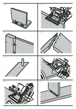
Page 3: ...1 Fig A 3 4 5 8 7 11 1 6 9 12 13 2 Fig B 12 14 12 13 XXXX XX XX 20 10 13 ...
Page 4: ...2 6 9 4 Fig C Fig D1 Fig D2 Fig E Fig F Fig G Fig H Fig I 1 11 8 6 2 15 7 23 ...
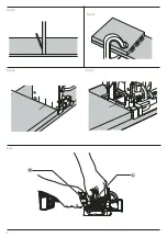
Page 6: ...4 5 7 5 cm 15 25 cm 15 25 cm Fig N3 Fig N4 Fig O Fig P1 Fig P2 Fig Q1 Fig Q2 Fig Q3 ...
Page 7: ...5 Fig R1 Fig R2 Fig S Fig T1 Fig T4 Fig U1 Fig T2 Fig T3 ...
Page 8: ...6 Fig U2 Fig U3 Fig U4 Fig U5 Fig V 3 18 ...
Page 50: ...48 Українська ...
Page 51: ...49 Українська ...
Page 52: ...530917 03 RUS UA 05 22 ...


