background image

Español 

36

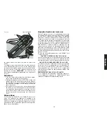
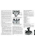
FIG. 2

GUARDA

ESCUADRA

DE LADO

DERECHO

PERILLA DE

ABRAZADERA

PASADOR DEL INGLETE

REGLA DE

INGLETE

AGUJEROS PARA 

MONTAR BANQUETA

PERILLA PARA SUJE-

TAR A ESCUADRA DE

LADO IZQUIERDO

PASADOR DE

SEGURIDAD

MANILLA DE OPERACIÓN

REGLA DE

BISEL

FIG. 3

D

C

B

A

FIG. 4

GATILLO 

INTERRUPTOR

MANILLA DE
OPERACIÓN

ESCUADRA GUÍA

IZQUIERDA

ESTÁTOR DEL

MOTOR

PALANCAS

DE

ANULACIÓN

DEL BISEL A

45º

CANALÓN

PARA EL

POLVO

TAPA DE

INSPECCIÓN DE

MOTOR

PERILLA DE
ANULACIÓN

DEL BISEL A 0º

PASADOR DE

SEGURIDAD

TOPE DE BISEL –

TRINQUETE DE 33,85º

MANILLA PARA

ACARREAR

LLAVE INGLESA

DE CUCHILLA

TORNILLO DE

AJUSTE DEL

TOPE DE BISEL

A 45º

SEGURO

DE LA

PERILLA

DE BISEL

INDENTACIONES

PARA LA MANO

TORNILLO DE

AJUSTE DE TOPE

DE BISEL A 0º

-DETAIL 1-

A

-DETAIL 2 -

BOTÓN PARA

FIJAR EJE

Summary of Contents for DW706

Page 1: ...RVICIO Y PÓLIZA DE GARANTÍA ADVERTENCIA LÉASE ESTE INSTRUCTIVO ANTES DE USAR EL PRODUCTO Before returning this product call 1 800 4 DEWALT IF YOU SHOULD EXPERIENCE A PROBLEM WITH YOUR DEWALT PURCHASE CALL 1 800 4 DEWALT IN MOST CASES A DEWALT REPRESENTATIVE CAN RESOLVE YOUR PROBLEM OVER THE PHONE IF YOU HAVE A SUGGESTION OR COMMENT GIVE US A CALL YOUR FEEDBACK IS VITAL TO THE SUCCESS OF DEWALT S Q...

Page 2: ...ARE TO TABLE 6 BEVEL STOP 6 FENCE ADJUSTMENT 6 AUTOMATIC ELECTRIC BRAKE 6 GUARD ACTUATION AND VISIBILITY 6 BRUSHES 7 CONTROLS 7 OPERATION 7 SWITCH 7 CUTTING WITH YOUR SAW 7 CROSSCUTS 7 BEVEL CUTS 7 QUALITY OF CUT 8 BODY AND HAND POSITION 8 CLAMPING THE WORKPIECE 8 SUPPORT FOR LONG PIECES 9 CUTTING PICTURE FRAMES SHADOW BOXES AND OTHER FOUR SIDED PROJECTS 9 CUTTING TRIM MOLDING AND OTHER FRAMES 9 C...

Page 3: ...at all times MAINTAIN TOOLS WITH CARE Keep tools sharp and clean for best and safest perfor mance Follow instructions for lubricating and changing accessories DISCONNECT TOOLS before servicing when changing accessories such as blades bits cutters etc REDUCE THE RISK OF UNINTENTIONAL STARTING Make sure switch is in OFF position before plugging in USE RECOMMENDED ACCESSORIES Consult the instruction ...

Page 4: ...old motor shaft DON T Force cutting action Stalling or partial stalling of motor can cause major dam age Allow motor to reach full speed before cutting DON T Cut ferrous metals Those with any iron or steel content or any masonry DON T Use abrasive wheels The excessive heat and abrasive particles generated by them will damage the saw DON T Allow anyone to stand behind saw DON T Apply lubricants to ...

Page 5: ...mooth Woodworking Large Carbide Molding Splinter Free Teeth Series 40 80 Laser Cut Body Fine Trim Ultra Smooth Woodworking Large Carbide Molding Splinter Free Teeth Decorative Hardwood Plywood Series 40 80 Laser Cut Body Melamines Ultra Smooth Woodworking Large Carbide Veneers Chip Splinter Teeth Special Laminates Free Tooth Geometry Series 40 60 Laser Cut Body Plastics Corian Very Smooth Woodwork...

Page 6: ...9 45 miter Max Height 3 5 Result Width 5 3 Max Width 5 6 Result Height 2 9 45 bevel Left Max Height 2 3 Result Width 7 4 Max Width 7 9 Result Height 1 9 45 bevel Right Max Width 7 9 Result Height 1 2 Max Height 1 6 Result Width 7 4 Your saw is capable of cutting baseboard moldings 0 9 thick by 6 0 tall on a 45 right or left miter DRIVE 120 Volt Motor 2200 Watts 15 Amp Motor 4000 RPM Cut Helical Ge...

Page 7: ...DLE BEVEL SCALE FIG 3 D C B A FIG 4 TRIGGER SWITCH OPERATING HANDLE LEFT SIDE FENCE MOTOR HOUSING 45 BEVEL OVERRIDE LEVERS DUST SPOUT MOTOR END CAP 0 BEVEL OVERRIDE KNOB LOCK DOWN PIN BEVEL STOP 33 85 PAWLS CARRY HANDLE BLADE WRENCH 45 BEVEL STOP ADJUSTMENT SCREW BEVEL LOCK KNOB HAND INDENTATIONS 0 BEVEL STOP ADJ SCREW DETAIL 1 A DETAIL 2 SPINDLE LOCK BUTTON ...

Page 8: ...n of the saw NEVER RAISE THE BLADE GUARD MANUALLY UNLESS THE SAW IS TURNED OFF FIG 5 FIG 8 Once made these adjustments should remain accurate Take a little time now to follow these directions carefully to maintain the accuracy of which your saw is capable MITER SCALE ADJUSTMENT FIG 5 Place a square against the saw s fence and blade as shown Do not touch the tips of the blade teeth with the square ...

Page 9: ... right pull the bevel stop knob The stop knob can be locked out by pulling the knob out and rotating it 180 45 BEVEL STOP OVERRIDES FIG 9 The bevel stop overrides are held secure with their attach ment screw to prevent inadvertent movement Use the bit on the blade wrench to loosen the attachment screw This allows the slides G to be pulled outward and the saw head to pivot past the 45 mark Be sure ...

Page 10: ... fits your needs Page 3 BODY AND HAND POSITION FIG 10 Proper positioning of your body and hands when operating the miter saw will make cutting easier more accurate and safer Never place hands near cutting area Place hands no closer than 6 from the blade Hold the workpiece tightly to the table and the fence when cutting Keep hands in posi tion until the trigger has been released and the blade has c...

Page 11: ...gree To use the vernier scale follow the steps listed below As an example let s assume that the angle you want to miter is 24 1 4 degree right 1 Turn off miter saw 2 Set the miter angle to the nearest whole degree desired by aligning the center mark in the vernier scale shown in figure V1 with the whole degree number etched in the miter scale Examine Figure V2 closely the setting shown is 24 degre...

Page 12: ...ees Most but not all crown molding has a top rear angle the section that fits flat against the ceiling of 52 degrees and a bottom rear angle the part that fits flat against the wall of 38 degrees Your miter saw has special pre set miter latch points at 31 62 FIG 16 FIG 17 FENCE TABLE CROWN MOLDING FLAT ON TABLE AND AGAINST FENCE CROWN MOLDING BETWEEN FENCE AND TABLE TABLE FENCE BOTTOM SIDE OF MOLD...

Page 13: ...Save left side of cut Special Cuts NEVER MAKE ANY CUT UNLESS THE MATERIAL IS SECURED ON THE TABLE AND AGAINST THE FENCE Aluminum Cutting ALWAYS USE THE APPROPRIATE SAW BLADE MADE ESPECIALLY FOR CUTTING ALUMINUM These are available at your local DEWALT retailer or DEWALT service center Certain workpieces due to their size shape or surface finish may require the use of a clamp or fixture to prevent ...

Page 14: ... 50 60 60 60 70 70 70 80 80 80 TABLE 1 COMPOUND MITER CUT POSITION WOOD WITH BROAD FLAT SIDE ON THE TABLE AND THE NARROW EDGE AGAINST THE FENCE SET THIS MITER ANGLE ON SAW S Q U A R E B O X 6 S I D E D B O X SET THIS BEVEL ANGLE ON SAW 8 S I D E D B O X ...

Page 15: ...r workmanship for three years from the date of purchase This warranty does not cover part failure due to normal wear or tool abuse For further detail of war ranty coverage and warranty repair information visit www dewalt com or call 1 800 4 DEWALT 1 800 433 9258 This warranty does not apply to accessories or dam age caused where repairs have been made or attempted by others This warranty gives you...

Page 16: ...COME UP TO SPEED WHAT S WRONG WHAT TO DO 1 Extension cord too light or too long 1 Replace with adequate size cord See page 1 2 Low house current 2 Contact your electric company TROUBLE MACHINE VIBRATES EXCESSIVELY WHAT S WRONG WHAT TO DO 1 Saw not mounted securely to stand or work bench 1 Tighten all mounting hardware See page 4 2 Stand or bench on uneven floor 2 Reposition on flat level surface S...

Page 17: ...EAU EN ÉQUERRE 21 BUTÉE DU BISEAU 21 RÉGLAGE DU GUIDE 22 FREIN ÉLECTRIQUE AUTOMATIQUE 22 VISIBILITÉ ET DÉCLENCHEMENT DU PROTÈGE LAME 22 BALAIS 22 COMMANDES 22 FONCTIONNEMENT 23 INTERRUPTEUR 23 MÉTHODES DE COUPE 24 COUPES TRANSVERSALES 24 COUPES EN BISEAU 24 QUALITÉ DE LA COUPE 24 POSITION DU CORPS ET DES MAINS 24 FIXATION DE L OUVRAGE 245 SUPPORT DE LONGS OUVRAGES 24 COUPE DE CADRES DE COFFRAGES O...

Page 18: ...ible de le fixer manuellement sur le plateau et contre le guide ou si les mains risquent de s approcher de moins de 15 cm 6 po de la lame NE PAS TROP ÉTENDRE LES BRAS les pieds doivent rester ancrés fermement sur le sol afin de maintenir son équilibre en tout temps BIEN ENTRETENIR L OUTIL afin d obtenir de meilleurs résultats et faire preuve de pru dence garder l outil propre et bien aiguisé Suivr...

Page 19: ...e l arbre ON DOIT maintenir la lame aiguisée ON DOIT s assurer que les entrées d air du moteur soient exemptes de copeaux et de poussière ON DOIT se servir des dispositifs de protection en tout temps y compris le protège lame ON DOIT garder les mains éloignées du trajet de la lame ON DOIT couper le courant débrancher le cordon et attendre que la lame s arrête com plètement avant de procéder à l en...

Page 20: ...le soulève le tube peut aussi être raccordé à un tube d aspiration Guide pour moulures en couronne DW7084 Permet d effectuer avec précision la coupe de moulures en couronne page 4 LAMES DE LA SCIE TOUJOURS UTILISER UNE LAME DE 30 5 cm 12 po À ORIFICE CENTRAL DE 2 54 cm 1 po LA VITESSE DOIT ÊTRE D AU MOINS 4 800 tr min On ne doit jamais utiliser une lame de dimension inférieure à celle recommandée ...

Page 21: ...te dernière au moyen de la poignée de trans port ou de la base indentée prévue à cet effet tel qu illustré à la figure 2 Montage sur un établi Les quatre pattes de la scie sont pourvues d orifices afin de faciliter le montage sur l établi tel qu illustré à la figure 2 Deux orifices de dimensions différentes sont fournis afin de pouvoir recevoir des vis de divers calibres il n est pas nécessaire d ...

Page 22: ...ÉE DE MANŒUVRE GUIDE GAUCHE CARTER DU MOTEUR LEVIERS DE SURPASSEMENT DE LA BUTÉE D ANGLE DE BISEAU DE 45º TUBE CHASSE POUSSIÈRE CAPUCHON D INSPECTION DES MOTEUR BOUTON DE SURPASSE MENT DE LA BUTÉE D ANGLE DE BISEAU DE 0º GOUPILLE DE VERROUILLAGE BUTÉE D ANGLE DE 33 85º CLIQUETS POIGNÉE DE TRANSPORT CLÉ DE RÉGLAGE DE LAME VIS DE RÉGLAGE DE LA BUTÉE D ANGLE DE BISEAU DE 45º BOUTON DE VERROUILLAGE D ...

Page 23: ...ent la marque de 45º tourner la vis de la butée jusqu à ce que cela se produise Pour régler la butée à un angle de 45º vers la droite desserrer la poignée et tirer sur le bouton de surpassement de la butée fig 2 pour passer par dessus la butée de 0º Si la scie est complète ment à droite et l indicateur ne pointe pas exactement la marque de 45º tourner la vis de la butée droite jusqu à ce que cela ...

Page 24: ...gle de 0º B Pour resserrer la poignée la tourner vers la droite Les marques indiquant les angles de biseau sont situées sur la partie avant inférieure du bras de la scie Fig 7C BOUTON DE SURPASSEMENT DE LA BUTÉE D ANGLE DE BISEAU DE 0º FIG 9 Le bouton de surpassement de la butée d angle de 0º B permet d effectuer des coupes en biseau vers la droite au delà de cette marque A B C C D E F RÉGLAGE DE ...

Page 25: ... La scie ainsi bloquée en position on peut la déplacer sans dan ger d un endroit à l autre Pour dégager la tête il suffit de la pencher de nouveau vers le bas et de retirer la goupille Fonctionnement Brancher la scie dans une prise de courant résidentielle de 60 Hz consulter la plaque signalétique afin de connaître la tension nominale de l outil S assurer que le cordon ne gêne pas les travaux INTE...

Page 26: ... sélectionner celles qui conviennent le mieux aux coupes requises POSITION DU CORPS ET DES MAINS FIGURE 10 Pour obtenir facilement et en toute sécurité une coupe pré cise le corps et les mains doivent être placés correcte ment Ne jamais mettre les mains à proximité de la zone de coupe les écarter d au moins 15 cm 6 po de la lame Durant la coupe maintenir solidement l ouvrage sur le plateau et cont...

Page 27: ...le pour l angle d onglet Régler ensuite les angles aux valeurs indiquées effectuer quelques coupes d essai et assembler les pièces ainsi obtenues afin de vérifier si elles conviennent et répéter jusqu à ce que les résultats soient satisfaisants Exemple si on fabrique une boîte à quatre côtés présentant un angle externe de 26 angle A à la figure 13 on doit utiliser la courbe située en haut à droite...

Page 28: ...ste ment précis Il EST EXTRÊMEMENT IMPORTANT DE S EXERCER SUR DES RETAILLES AVANT DE COMMENCER COUPES DE MOULURES EN COURONNE À PLAT AU MOYEN D ANGLES COMBINÉS 1 1 Coucher la moulure le dos contre le plateau figure 17 2 Les réglages décrits ci dessous s appliquent aux moulures en couronne standard normes américaines présentant des angles de 52 et de 38 degrés RÉGLAGE DU BISEAU TYPE DE COUPE Gauche...

Page 29: ...20 20 20 30 30 30 40 40 40 50 50 50 60 60 60 70 70 70 80 80 80 TABLEAU 1 ONGLETS MIXTES REGLAGE DE L ANGLE DU BISEAU RÉGLER LA SCIE À CET ANGLE D ONGLET B O Î T E À 8 C Ô T É S B O Î T É À 6 C Ô T É S B O Î T E C A R R É E ...

Page 30: ...OURS UTILISER UNE LAME SPÉCIALEMENT CONÇUE POUR CET USAGE celles ci sont vendues séparément chez un dépositaire local ou aux centres de service DEWALT Certains ouvrages selon la dimension la forme et le fini de la surface peuvent nécessiter l utilisation d une bride de serrage ou d une ferrure afin d en empêcher le mouvement durant la coupe La figure 18 montre comment placer l ouvrage afin de coup...

Page 31: ... DEWALT réparera sans frais tout produit défectueux causé par un défaut de matériel ou de fabrication pour une période de trois ans à compter de la date d achat La présente garantie ne couvre pas les pièces dont la défectuosité a été causée par une usure normale ou l usage abusif de l outil Pour obtenir de plus amples renseignements sur les pièces ou les réparations couvertes par la présente garan...

Page 32: ...t 1 La remplacer par une rallonge appropriée Consulter la page 16 2 L alimentation électrique est insuffisante 2 Appeler la compagnie d électricité PROBLÈME L OUTIL VIBRE EXCESSIVEMENT QUE SE PASSE T IL QUOI FAIRE 1 La scie n est pas fixée solidement sur le support ou l établi 1 Serrer tous les éléments de montage Consulter la page 20 2 Le support ou l établi est sur une surface inégale 2 Le place...

Page 33: ...PE DE BISEL 37 REGULACIÓN DE ESCUADRA DE GUÍA 37 FRENO ELÉCTRICO AUTOMÁTICO 38 ACTUACIÓN Y VISIBILIDAD DE LA GUARDA 38 CEPILLOS 38 CONTROLES 38 FUNCIONAMIENTO 38 INTERRUPTOR 39 CORTANDO CON SU SIERRA 39 CORTES TRASVERSALES 39 CORTES DE BISEL 39 CALIDAD DEL CORTE 40 POSICIÓN DEL CUERPO Y LAS MANOS 40 SUJETAMIENTO DE LA PIEZA 40 SOPORTE DE PIEZAS LARGAS 40 CORTE DE MARCOS ENMARCAMIENTOS DE CAJA Y OT...

Page 34: ...ridad SUJETE EL TRABAJO Use abrazaderas o sujetadores cuando no pueda afirmar la pieza de trabajo en la mesa o contra la escuadra con la mano o cuando su mano quede peligrosamente cerca de la hoja a una distancia de 6 o menos NO SE EXTIENDA DEMASIADO Mantenga el equilibrio en todo momento MANTENGA LAS HERRAMIENTAS CON CUIDADO Mantenga las herramientas afiladas y limpias para que funcionen en forma...

Page 35: ...Co 701 East Joppa Road Baltimore MD 21286 o llame al 1 800 433 9258 Asegúrese de que todas las arandelas de la hoja de la sierra estén limpias y los lados empo trados del anillo estén contra la hoja Apriete bien el tornillo de árbol Mantenga la hoja de la sierra afilada Mantenga las ranuras de aire del motor libres de astillas y mugre Use guardas para las cuchillas en todo momento Mantenga las man...

Page 36: ...OS PARA EL EJE DE 1 CLASIFICADAS PARA VELOCIDAD DE POR LO MENOS 4800 RPM Nunca use una hoja de menor diámetro No quedaría bien protegida CUCHILLAS Nº DE DESC DE APLICACIÓN TIPO DE DEWALT DIENTES CUCHILLA CORTE Serie 20 40 Placa delgada Fines generales Liso Construcción Borde pintado Arquitraves Sin astillas Libre amarillo adornos estructura Serie 20 60 Placa delgada Arquitraves finos Muy liso Cons...

Page 37: ... tornillo de la sierra D Apriete con firmeza usando el pasador de cierre y la llave suministrada rosca hacia la izquierda Cuando use agujeros de 5 8 saque el adapta Para desempacar su sierra Verifique el contenido de la caja de la sierra de ingletes para confirmar que haya recibido todas las piezas Además de este manual de instrucción la caja debe contener 1 Una sierra de ingletes Nº DW706 2 Una c...

Page 38: ...RRUPTOR MANILLA DE OPERACIÓN ESCUADRA GUÍA IZQUIERDA ESTÁTOR DEL MOTOR PALANCAS DE ANULACIÓN DEL BISEL A 45º CANALÓN PARA EL POLVO TAPA DE INSPECCIÓN DE MOTOR PERILLA DE ANULACIÓN DEL BISEL A 0º PASADOR DE SEGURIDAD TOPE DE BISEL TRINQUETE DE 33 85º MANILLA PARA ACARREAR LLAVE INGLESA DE CUCHILLA TORNILLO DE AJUSTE DEL TOPE DE BISEL A 45º SEGURO DE LA PERILLA DE BISEL INDENTACIONES PARA LA MANO TO...

Page 39: ...superior del brazo de la sierra e indentaciones para la mano en la base tal como se muestra en la Ilustración 4 Correcciones HAGA TODOS LOS AJUSTES CUANDO LA SIERRA DE INGLETES ESTÉ DESENCHUFADA NOTA Su sierra de ingletes se regula en forma precisa y completa en la fábrica en el momento de su fabricación Si requiriese una nueva regulación debido al transporte y empaquetado o por cualquier otra raz...

Page 40: ...en su funcionamiento hasta que los cepillos estén asentados Cuando la esté haciendo correr sola NO ATE PEGUE NI FIJE DE NINGUNA OTRA FORMA EL GATILLO EN POSICIÓN DE ENCENDIDO SOSTENGA CON LA MANO SOLAMENTE Controles Su sierra de ingletes compuesta tiene varios controles prin cipales que se describirán brevemente aquí Para mayor información sobre esos controles veánse las respectivas secciones post...

Page 41: ...apretando el gatillo interruptor Cuando la sierra gane velocidad cerca de 1 segundo baje el brazo suave y lentamente para cortar la madera Deje que la cuchilla pare completamente antes de levantar el brazo Los cortes a inglete se hacen con el brazo de la sierra a un cierto ángulo que no sea cero Ese ángulo es a menudo de 45 grados para hacer esquinas pero se puede poner en cualquiera posición entr...

Page 42: ...de 90º Para hacer este tipo de empalme ponga el bisel a cero y la guía de inglete a 45º Reiteramos la posición de la madera está con el lado ancho y plano sobre la mesa y el borde delgado contra la escuadra de guía Los dos diagramas en la Ilustración 11 son para objetos de cuatro lados solamente Como el número de lados cambia así también cambian los ángulos de ingletes y de bisel La lista de abajo...

Page 43: ...e alinee con la marca del grado MÁS CERCANO en la regla de ingletes En nuestro ejemplo la marca del grado más cercano en la regla de ingletes es de 25º La ilustración V2 muestra un valor de 24 1 2 grados de inglete a la derecha Para fijar valores que exigen fracciones de grado 1 4 1 2 3 4 grados alinee la marca de ninio deseada con la marca del grado MÁS CERCANO en la regla de ingletes tal como se...

Page 44: ...GUÍA MOLDURA CORONADA ENTRE LA ESCUADRA GUÍA Y LA MESA MESA ESCUADRA DE GUÍA LADO DE ABAJO DE LA MOLDURA LADO SUPERIOR DE LA MOLDURA FIG 17A CORONA DW7084 Al fijar los ángulos de bisel y de inglete para todos los cortes compuestos recuerde que Los ángulos presentados para las moldurass coronadas son muy precisos y difíciles de fijar con precisión Dado que pueden cambiar fácilmente y muy pocas habi...

Page 45: ... 40 40 40 50 50 50 60 60 60 70 70 70 80 80 80 TABLA 1 CORTE DE INGLETE COMPUESTO AJUSTE ESTE ANGULO DE INGLETE EN LA SIERRA C A J A C U A D R A D A C A J A H E X A G O N A L AJUSTE ESTE ANGULO DE BISELEN LA SIERRA C A J A O C T A G O N A L ...

Page 46: ...i llega el caso la sierra funcionará en forma apropiada y hará el corte más grande NUNCA AMARRE FIJE CON UNA CINTA ADHESIVA NI SOSTENGA DE ALGUNA OTRA FORMA LA GUARDA ABIERTA CUANDO TRABA JE CON LA SIERRA Saque y cambio de la correa La correa está diseñada para durar todo el tiempo que dure la herramienta No obstante el uso excesivo de ésta causa la rotura de la correa Si la hoja no da vueltas cua...

Page 47: ...a no será válida en los siguientes casos Cuando el producto se hubiese utilizado en condiciones distintas a las normales Cuando el producto no hubiese sido operado de acuer do con el instructivo de uso que se acompaña Cuando el producto hubiese sido alterado o reparado por personas distintas a las enlistadas al final de este certificado Anexo encontrará una relación de sucursales de servicio de fá...

Page 48: ... El cordón de extensión es demasiado ligero o demasiado largo 1 Reemplace con un cordón de dimensión adecuada Véase página 33 2 Baja corriente en la casa 2 Contacte la compañía de electridad PROBLEMA LA MÁQUINA VIBRA EXCESIVAMENTE QUÉ PASA QUÉ HACER 1 La sierra no está montada bien al soporte o mesa de trabajo 1 Apriete dispositivos de montaje Véase página 36 2 El soporte o mesa está sobre piso di...

Page 49: ...6 DW706 220 Copyright 2000 2003 2004 DEWALT The following are trademarks for one or more DEWALT power tools the yellow and black color scheme the D shaped air intake grill the array of pyramids on the handgrip the kit box configuration and the array of lozenge shaped humps on the surface of the tool ...

Reviews: