DS525 MOBILELOCK
TM
Equipment
Power Adapter
For use only with the D
e
wAlt Ds500.
not For use on equipment sources other
thAn 12 V or 24 V.
WARNING: Read and understand all instructions and
warnings for this product.
In addition, read and follow all
instructions and warnings provided with the DS500 MOBILELOCK™
GPS Locator with Anti-Theft Alarm (Base Unit).
CAUTION: POTENTIAL EQUIPMENT MALFUNCTION OR
FAILURE.
Do not operate with a damaged power supply cord or plug.
Damage to the hardware may occur. Protect the power supply cord
from cutting, fraying and other damage particularly at plugs and the
point where they exit from the product. Do not pull on cords or cables.
If a cord or plug is damaged, have it replaced immediately.
CAUTION: POTENTIAL EQUIPMENT MALFUNCTION OR
FAILURE.
Do not remove or by-pass the fuse in the cord of the
DS525. Do not remove or by-pass any overload protection device
currently in the equipment/vehicle.
Important
• This product should be installed by a professional. Refer to the
installation instructions in this manual and the instruction sheet
included with the connectors.
• This product is not user serviceable. There are no user serviceable
parts inside the product. Servicing at a D
e
WALT authorized service
center is required to avoid damage to the product. Unauthorized
service will void the warranty.
• MOBILELOCK™ is a trademark of SITELOCK LLC. All other
trademarks in this manual are the properties of their respective
owners.
Product Overview
The DS525 Equipment Power Adapter is designed to use a 12 V or
24 V battery to provide power to the DS500 MOBILELOCK™. The
DS525 consists of an input cable, a DC to DC converter, an output
cable and connectors. The DS500 will recharge regardless of whether
the heavy equipment or vehicle is running.
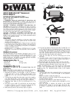
Components (Fig. 1)
A. Black cable
D. Fuse
B. Red cable
E. Output cable
C. Connectors
Installation (Fig. 2, 3)
WARNING: To reduce the risk of personal injury, turn off
ignition switch.
note:
If the DS525 is wired incorrectly, it will not work. Neither the
DS525 nor the equipment’s electrical system will be damaged.
1. Determine the positive (+) and negative (-) wires to be spliced
coming from the 12 V or 24 V battery of the equipment. The
connections to be used should be independent of the ignition
switch.
2. The negative connection should be made to a ground or negative
wire. Slide the negative (-) wire from the battery supply of the
equipment into the pass through slot of the second connector.
3. Insert the black cable (A) into the half-through slot of the
connector.
4. Use pliers to press metal “U” contact down into the connector
as shown in Figure 2. As the “U” contact is pressed into the
connector, it grasps conductor as it displaces insulation.
5. Bend plastic cover and snap closed as shown in Figure 3.
6. The positive connection should be made with a wire that has 12 V
or 24 V when the ignition is off. Slide the positive (+) wire from the
battery supply of the equipment into the pass-through slot of the
connector. The cable must be protected by a fuse installed directly
next to the power connection. Do not cut the cable. If a shorter
cable is desired, wrap the cable with a cable tie.
7. Insert the red cable (B) into the half-through slot of the
connector.
8. Use pliers to press metal “U” contact down into connector as
shown in Figure 2. As the “U” contact is pressed into connector, it
grasps conductor as it displaces insulation.
9. Bend plastic cover over and snap closed as shown in Figure 3.
10. Mount the DS525 using the screw holes. Do not drill or screw
into vehicle system components such as wires, hoses, etc.
note:
The DS500 draws a very small amount of current while
charging. If the equipment/vehicle is not started over an extended
period of time, the equipment/vehicle battery could become
discharged.
Mounting
• Install the DS525 when the equipment/vehicle is on level ground
and the brake is on. Turn off the engine of the equipment/
vehicle.
• Mount in a location to protect from damage.
• Mount securely to prevent the DS525 from coming loose during
equipment/vehicle operation.
• Do not mount near engine or other extreme heat source.
• Do not drill or screw into vehicle system components such as
wires, hoses, etc.
• After the DS525 is installed, the battery of the DS500
MOBILELOCK™ charges for up to 24 hours. During this time,
an increase in energy may cause the DS525 to be warm to the
touch.
SITELOCK LLC, 701 East Joppa Road, Baltimore, MD 21286 (JUL07) Form No. 654664-00 DS525 Copyright © 2007 D
e
WALT
E
B
FIg. 1
A
D
C
FIg. 3
FIg. 2


