DeWalt DCE400B Manual Download Page 9

English

9

The belt hook can be be attached to either side of the tool 
using only the screw provided, to accommodate left- or 
right- handed users. If the hook is not desired at all, it can be 
removed from the tool.
To move the belt hook, remove the screw that holds the 
belt hook in place then reassemble on the opposite side. Be 
sure to securely tighten the screw.

OPERATION


WARNING: To reduce the risk of serious personal 
injury, turn unit off and remove the battery pack 
before making any adjustments or removing/
installing attachments or accessories.

 An 

accidental start-up can cause injury.


WARNING: Proper material preparation 
and installation is the responsibility of the 
installing contractor. 


WARNING:


The tubing and hardware must be 

used in compliance with applicable building 
codes and as approved by the authorities having 
jurisdiction.

 For proper installation procedures 

and to reduce the risk of failure resulting in injury or 
property damage, follow all published safety and 
installation instructions.


CAUTION:

 Pinch hazard. Keep fingers away from 

expander head while in use.

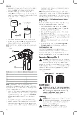
Installing and Removing the Battery Pack 
(Fig. E)

nOTE:

 For best results, make sure your battery pack is 

fully charged.
To install the battery pack 

 9 

 into the tool handle, align the 

battery pack with the rails inside the tool’s handle and slide 
it into the handle until the battery pack is firmly seated in 
the tool and ensure that it does not disengage.
To remove the battery pack from the tool, press the release 
button 

 10 

 and firmly pull the battery pack out of the tool 

handle. Insert it into the charger as described in the charger 
section of this manual.

Fig. E

10

9

Proper Hand Position (Fig. F)


WARNING:

 To reduce the risk of serious personal injury, 

ALWAYS

 use proper hand position as shown. 


WARNING:

 To reduce the risk of serious personal 

injury, 

ALWAYS

 hold securely in anticipation of a 

sudden reaction.

Proper hand position requires one hand on the main 
handle 

 3 

Fig. F

3

Trigger Switch and Lock Off (Fig. A)

To turn the tool on, squeeze the trigger switch 

 4 

. To turn 

the tool off, release the trigger switch.
Your PEX expander is equipped with a trigger lock 

 5 

. To 

lock the trigger switch in the OFF postition, push the trigger 
lock from the left side of the tool. To unlock the trigger 
switch, push the trigger lock from the right side of the tool.

nOTE:

 Depressing the trigger switch will activate the LED 

worklight 

 6 

. The light will dim after two and half minutes 

and will automatically turn off after three minutes. To turn 
the light off immediately, remove and reinstall the battery. 
The worklight is for lighting the immediate work surface and 
is not intended to be used as a flashlight.

NOTICE: 

To reduce the chance of damge to the tool


ALWAYS

 lock the tool when not in use. 

Creating a PEX Tubing Connection 
(Fig. A, G, H)


WARNING:


Prior to use inspect all workpieces 

for cracks, defects or wear.

 Defective workpieces 

may shatter.


CAUTION:

 Using incorrectly sized expansion heads 

may result faulty connection, possibly resulting in 
damage to property.

To create a proper PEX tubing connection:

1.  Select appropriate expander head 

 1 

 to match the 

tubing and, if needed, remove any dirt and debris.

2.  Using a clean, lint-free cloth, apply a thin coat of 

D

e

WALT

 DCE400GR grease to the expander cone 

 2 

DO nOT

 over-lubricate.

Summary of Contents for DCE400B

Page 1: ... injury Used without word Indicates a safety related message NOTICE Indicates a practice not related to personal injury which if not avoided may result in property damage WARNING Read all safety warnings instructions illustrations and specifications provided with this power tool Failure to follow all instructions listed below may result in electric shock fire and or serious injury WARNING To reduc...

Page 2: ...ent Always wear eye protection Protective equipment such as dust mask non skid safety shoes hard hat or hearing protection used for appropriate conditions will reduce personal injuries c Prevent unintentional starting Ensure the switch is in the off position before connecting to power source and or battery pack picking up or carrying the tool Carrying power tools with your finger on the switch or ...

Page 3: ...hands can be pinched if they become caught in the attachments Inspect tool and attachments before use Never attempt to repair or use a damaged expander head or other attachment Replace with a new expander head This tool produces large forces that can break attachments or parts and cause injury Always be attentive and take proper safety precautions including wearing eye protection Only trained pers...

Page 4: ... manual for compatibility of chargers and battery packs READ ALL INSTRUCTIONS Important Safety Instructions for All Battery Packs WARNING Read all safety warnings and all instructions for the battery pack charger and power tool Failure to follow the warnings and instructions may result in electric shock fire and or serious injury Do not charge or use the battery pack in explosive atmospheres such ...

Page 5: ...ng might indicate 120 Wh 1 battery implied Fuel Gauge Battery Packs Fig B Some DeWALT battery packs include a fuel gauge which consists of three green LED lights that indicate the level of charge remaining in the battery pack The fuel gauge is an indication of approximate levels of charge remaining in the battery pack according to the following indicators 75 100 charged 51 74 charged 50 charged Pa...

Page 6: ...ottom of the housing Do not operate the charger with a damaged cord or plug Do not operate the charger if it has received a sharp blow been dropped or otherwise damaged in any way Take it to an authorized service center Do not disassemble the charger take it to an authorized service center when service or repair is required Incorrect reassembly may result in a risk of electric shock electrocution ...

Page 7: ...CB113 DCB115 DCB118 DCB132 These chargers are designed to be wall mountable or to sit upright on a table or work surface If wall mounting locate the charger within reach of an electrical outlet and away from a corner or other obstructions which may impede air flow Use the back of the charger as a template for the location of the mounting screws on the wall Mount the charger securely using drywall ...

Page 8: ...it off and remove the battery pack before making any adjustments or removing installing attachments or accessories An accidental start up can cause injury Installing and Removing the Expander Head Fig A D To install an expander head 1 screw onto the tool clockwise until hand tight DO NOT over tighten To uninstall an expander head unscrew from the tool counterclockwise NOTICE To reduce the chance o...

Page 9: ...y pack out of the tool handle Insert it into the charger as described in the charger section of this manual Fig E 10 9 Proper Hand Position Fig F WARNING Toreducetheriskofseriouspersonalinjury ALWAYS useproperhandpositionasshown WARNING Toreducetheriskofseriouspersonal injury ALWAYS holdsecurelyinanticipationofa suddenreaction Proper hand position requires one hand on the main handle 3 Fig F 3 Tri...

Page 10: ...new PEX Ring Making 3 8 PEX Tubing Connections Fig A G The thicker 3 8 PEX rings will not fit over 3 8 PEX tubing without first expanding each end of the PEX ring 1 Insert the expander head 1 into the PEX ring 11 2 Squeeze the trigger switch 4 and allow the expander head to exapand the PEX ring once 3 Remove the PEX ring and repeat steps 1 and 2 for the other end of the PEX ring 4 IMMEDIATELY slid...

Page 11: ...rship will serve as your proof of purchase FOR YOUR SAFETY Registering your product will allow us to contact you in the unlikely event a safety notification is required under the Federal Consumer Safety Act Register online at www dewalt com register Three Year Limited Warranty DeWALT will repair without charge any defects due to faulty materials or workmanship for three years from the date of purc...

Page 12: ...tubing removed while the expander cone was in the expanded postion Cut 2 50 mm from the PEX tubing and restart the process Is the PEX tubing and Ring dry Wipe dry with a clean lint free cloth Is there grease from the expander head inside the PEX tubing Wipe off all grease from inside the PEX tubing and relubricate the expander head The Ring slides during the expansion process Is the PEX tubing and...

Reviews: