background image

8

Drilling with a Solid Bit (Fig. 1)

  1. Insert the appropriate drill bit.
  2. Set the mode selector switch (F) to the hammerdrilling position.
  3. Set the electronic speed and impact control dial (G).
  4. Fit and adjust the side handle (C).
  5. Mark the spot where the hole is to be drilled.
  6. Place the drill bit on the spot and switch on the tool.
  7. Always switch off the tool when work is finished and before unplugging.

Drilling with a Core Bit (Fig. 1)

  1. Insert the appropriate core bit.
  2. Assemble the centerdrill into the core bit.
  3. Set the mode selector switch (F) to the hammerdrilling position.
  4. Turn the electronic speed and impact control dial (G) to a medium or high speed 

setting.

  5. Fit and adjust the side handle (C).
  6. Place the centerdrill on the spot and switch on the tool. Drill until the core 

penetrates into the concrete approx. 1 cm.

  7. Stop the tool and remove the centerdrill. Place the core bit back into the hole and 

continue drilling.

  8. When drilling through a structure thicker than the depth of the core bit, break 

away the round cylinder of concrete or core inside the bit at regular intervals.

    To avoid unwanted breaking away of concrete around the hole, first drill a hole 

the diameter of the centerdrill completely through the structure. Then drill the 

cored hole halfway from each side.

  9. Always turn the tool off when work is finished and before unplugging.

Chipping and Chiselling (Fig. 1)

  1. Insert the appropriate chisel and rotate it by hand to lock it into one of 

18 positions.

  2. Set the mode selector switch (F) to the hammering only position.
  3. Set the electronic speed and impact control dial (G).

WARNING: 

The use of a residual current device (RCD) protected supply with a 

rated residual current of 30 mA or less is recommended. The use of a RCD reduces 

the risk of electric shock.
Hold tool with both hands to maximize control.

Trigger Switch (Fig. 1) 

To turn the tool on, depress the trigger switch (A). 
To stop the tool, release the trigger switch. 
The lock-on slider (B) allows the trigger switch (A) to be locked on in chiselling mode 

only. If the lock-on button is activated in drilling mode, as a feature the tool will switch 

off automatically.
To turn the tool on, press the trigger switch (A).
To stop the tool, release the switch.
For continuous operation, press and hold down the switch (A), slide the lock-on 

button (B) upwards and release the switch.
To stop the tool in continuous operation, press the switch briefly and release it. 

Always switch off the tool when work is finished and before unplugging.

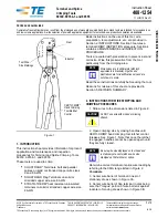
Proper Hand Position (Fig. 6) 

D

FIG. 6

C

WARNING: 

To reduce the risk of 

serious personal injury, 

ALWAYS

 use 

proper hand position as shown. 

WARNING:

 To reduce the risk of 

serious personal injury, 

ALWAYS

 hold 

securely in anticipation of a sudden 

reaction. 

Proper hand position requires one hand 

on the side handle (C), with the other 

hand on the main handle (D). 

Hammerdrilling

To turn the tool on, press the on/off 

switch (A).
To stop the tool, release the switch.

Summary of Contents for D25712-XE

Page 1: ...D25712 XE 48 mm 1 7 8 SDS MAX COMBINATION HAMMER INSTRUCTION MANUAL ...

Page 2: ...ttered or dark areas invite accidents b Do not operate power tools in explosive atmospheres such as in the presence of flammable liquids gases or dust Power tools create sparks which may ignite the dust or fumes c Keep children and bystanders away while operating a power tool Distractions can cause you to lose control 2 ELECTRICAL SAFETY a Power tool plugs must match the outlet Never modify the pl...

Page 3: ...or binding of moving parts breakage of parts and any other condition that may affect the power tool s operation If damaged have the power tool repaired before use Many accidents are caused by poorly maintained power tools f Keep cutting tools sharp and clean Properly maintained cutting tools with sharp cutting edges are less likely to bind and are easier to control g Use the power tool accessories...

Page 4: ...cessible metal parts on the tool and bits may get extremely hot during operation Small bits of broken material may damage bare hands Never lay the tool down until the bit has come to a complete stop Moving bits could cause injury Do not strike jammed bits with a hammer to dislodge them Fragments of metal or material chips could dislodge and cause injury Slightly worn chisels can be resharpened by ...

Page 5: ... WARNING We recommend the use of a residual current device with a residual current rating of 30mA or less The label on your tool may include the following symbols The symbols and their definitions are as follows V volts A amperes Hz hertz W watts min minutes alternating current direct current alternating or direct current Class I Construction no no load speed grounded earthing terminal Class II Co...

Page 6: ...etely worn out refer to Brushes under Maintenance Fully Vibration dampened Main Handle Fig 1 The dampers in the side handle C absorb the vibrations transmitted to the user This improves user comfort during the operation SAVE THESE INSTRUCTIONS FOR FUTURE USE Motor Your DEWALT tool is powered by a DEWALT built motor Be sure your power supply agrees with the nameplate markings Voltage decrease of mo...

Page 7: ...gle of approx 20 for optimum control 5 Lock the side handle mounting assembly in place by tightening the clamp wheel H MOUNTING IN REAR POSITION FIG 2B The rear position is particularly useful when drilling down into a floor 1 Unscrew the side handle C and remove it from the front position Leave the side handle mounting assembly in front position 2 Screw the side handle directly into one of the re...

Page 8: ...ounters re bar or other foreign substances Clutch Setting 80 Nm V is designed for higher torque applications such as core bits and deep hole drilling and is designed to clutch out at a higher torque threshold NOTE Allow the motor housing to rotate a little while changing torque Each time the tool is plugged in it will automatically default to clutch setting 1 into clutch setting 40 Nm U the most s...

Page 9: ... and Chiselling Fig 1 1 Insert the appropriate chisel and rotate it by hand to lock it into one of 18 positions 2 Set the mode selector switch F to the hammering only position 3 Set the electronic speed and impact control dial G WARNING The use of a residual current device RCD protected supply with a rated residual current of 30 mA or less is recommended The use of a RCD reduces the risk of electr...

Page 10: ...ent including brush inspection and replacement should be performed by certified service centers or other qualified service organizations always using identical replacement parts ACCESSORIES WARNING Since accessories other than those offered by DEWALT have not been tested with this product use of such accessories with this tool could be hazardous To reduce the risk of injury only DEWALT recommended...

Page 11: ... Year Warranty is not applicable to items deemed as consumables Radial arm saws are covered by a one 1 year warranty only DEWALT Reserves the right to review its warranty policy prior to launch of any new business development products 30 DAY NO SATISFACTION GUARANTEE If you are dissatisfied with any DEWALT power tool laser or nailer for any reason simply return it to the point of purchase with you...

Page 12: ...a JUN10 Part No N081422 D25711 XE Copyright 2010 DEWALT The following are trademarks for one or more DEWALT power tools the yellow and black color scheme the D shaped air intake grill the array of pyramids on the handgrip the kit box configuration and the array of lozenge shaped humps on the surface of the tool ...

Reviews: