DeVilbiss MG5-OLSTAT-3A User Manual Download Page 10

10

UNIT CYCLES AUTOMATICALLY WHEN POWER IS ON. DURING MAINTENANCE, YOU COULD BE EXPOSED TO VOLTAGE
SOURCES, COMPRESSED AIR OR MOVING PARTS. PERSONAL INJURIES CAN OCCUR. UNPLUG THE UNIT AND BLEED OFF ALL
AIR TANK PRESSURE BEFORE DOING ANY MAINTENANCE OR REPAIR. NEVER OPERATE THE UNIT WITH THE BELT GUARD
REMOVED.

2. Increase frequency of oil changes if humidity or operating

conditions are extreme.

Every 160 Hours of Operation:

1. Check drive belt tension; adjust if necessary. (Refer to SER-

VICE INSTRUCTIONS in this manual.)

2. Inspect air lines and fittings for leaks; correct as necessary.
3. Check the alignment of the motor pulley to the flywheel. If

necessary, align to within 1/32 inch on center line.

Each Year of Operation or if a Problem
is Suspected:

Check condition of air compressor pump intake and exhaust
valves. Replace if damaged or worn out.

MAINTENANCE

Normal Operation (cont'd)

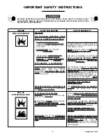
TOO MUCH AIR PRESSURE CAUSES A HAZ-
ARDOUS RISK OF BURSTING. CHECK THE
MANUFACTURER'S MAXIMUM PRESSURE
RATING FOR AIR TOOLS AND ACCESSORIES.
THE REGULATOR OUTLET PRESSURE MUST
NEVER EXCEED THE MAXIMUM PRESSURE
RATING. ON MODELS HAVING ONLY A SHUT-
OFF VALVE, YOU MUST INSTALL A REGULA-
TOR BEFORE USING ACCESSORIES RATED AT
LESS THAN 125 PSIG.

3. Turn the pressure switch lever to the "ON-AUTO" position and

allow tank pressure to build. The motor will stop when tank
pressure reaches cut-out pressure. Slowly release air pres-
sure from globe valve.

4. The compressor is now ready for use.

6. After the water has been drained, close the drain cock. The air

compressor can now be stored

.

NOTE

If  the drain cock valve is plugged, release all
air pressure. The valve can then be removed,
cleaned and reinstalled.

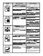
DRAIN TANK DAILY. WATER WILL CONDENSE
IN THE AIR TANK. IF NOT DRAINED, WATER
WILL CORRODE AND WEAKEN AIR TANK,
CAUSING A RISK OF AIR TANK RUPTURE.

OPERATING PROCEDURES (cont'd)

5.

When You Are Finished:

 drain tank pressure at approxi-

mately 20 PSI, open the drain valve and allow moisture to drain.

Routine Maintenance Schedule

Daily:

1. Check oil level. Add if necessary.
2. Drain water from the air tank, any moisture separators or

transformers.

3. Check for any unusual noise and/or vibration.
4. Manually check all safety valves to make sure they are

operating properly.

5. Inspect for oil leaks and repair any leaks found.
6. Inspect air filter, replace if necessary.

Every 40 Hours of Operation:

1. Inspect condition of drive belt; replace if necessary

Every 100 Hours of Operation:

1. Drain and refill compressor crankcase with 16 fluid ounces

(473.2 ml) of clean compressor oil such as Castrol Heavy Duty
30 weight.

To ensure efficient operation and longer life of the air compressor outfit, a routine maintenance schedule should be prepared and followed.
The following routine maintenance schedule is geared to an outfit in a normal working environment operating on a daily basis. If necessary,
the schedule should be modified to suit the conditions under which your compressor is used. The modifications will depend upon the hours
of operation and the working environment. Compressor outfits in an extremely dirty and/or hostile environment will require a greater
frequency of all maintenance checks.

Summary of Contents for MG5-OLSTAT-3A

Page 1: ...ve the following information Model number of your product Part number and description of the item you wish to purchase Retain Original Sales Receipt as Proof of Purchase for Warranty Repair Work TABLE OF CONTENTS SAFETY GUIDELINES 1 WARRANTY STATEMENT 2 WARNING CHART 3 4 SPECIFICATIONS 5 GLOSSARY 5 DUTY CYCLE 5 GENERAL INFORMATION 5 ON RECEIPT INSPECTION 5 DESCRIPTION OF OPERATION 6 INSTALLATION A...

Page 2: ...t Authorized Warranty Service Center that provides on site service calls for service call arrangement If the purchaser does not receive satisfactory results from the Authorized Warranty Service Center the purchaser should contact DeVilbiss Air Power Company ExCell Manufacturing Merchandise sold as reconditioned floor models and or display models Any damaged or incomplete equipment sold as is Merch...

Page 3: ...TTACHMENTS THE TANK IS DESIGNED TO WITHSTAND SPECIFIC OPERATING PRESSURES NEVER MAKE ADJUSTMENTS OR PARTS SUBSTI TUTIONS TO ALTER THE FACTORY SET OPERATING PRESSURES FOR ESSENTIAL CONTROL OF AIR PRES SURE YOU MUST INSTALL A PRESSURE REGULATOR AND PRESSURE GAUGE TO THE AIR OUTLET OF YOUR COMPRESSOR FOLLOW THE EQUIPMENT MANUFACTUR ERS RECOMMENDATION AND NEVER EXCEED THE MAXIMUM ALLOWABLE PRES SURE R...

Page 4: ...OMPONENTS REMOVED OR DAMAGE ANY ELECTRICAL WIRING OR REPAIRS RE QUIRED ON THIS PRODUCT SHOULD BE PERFORMED BY AUTHORIZED SERVICE CEN TER PERSONNEL IN ACCORDANCE WITH NATIONAL AND LOCAL ELECTRICAL CODES MAKE CERTAIN THAT THE ELECTRICAL CIRCUIT TO WHICH THE COMPRESSOR IS CONNECTED PROVIDES PROPER ELECTRICAL GROUNDING CORRECT VOLTAGE AND AD EQUATE FUSE PROTECTION ALWAYS WEAR ANSI Z87 1 APPROVED SAFET...

Page 5: ... 50 of one hour is DUTY CYCLE considered misuse because the air compressor is undersized for the required air demand Maximum compressor pumping time per hour is 30 minutes You have purchased an air compressor unit consisting of an aluminum 2 cylinder single stage air compressor pump with cast iron sleeves an air tank and associated controls and instru ments You will also find a Parts Manual Your a...

Page 6: ... end of each use Air Intake Filter This filter is designed to clean air coming into the pump This filter must always be clean and ventilation openings free from obstructions See Maintenance AirCompressorPump Tocompressair thepistonsmovesupand down in the cylinder On the downstroke air is drawn in through the airintakevalves Theexhaustvalveremainsclosed Ontheupstroke of the piston air is compressed...

Page 7: ...ious damage may result if the following break in instructions are not closely followed Break in Procedures Wiring Instructions Perform electrical wiring according to the following instructions Install the compressor outfit as close to the main power supply as possible This practice will avoid using long lengths of electrical wiringforthepowersupplywhichcancausepowerlossanddamage to the motor When ...

Page 8: ...g It is recommended that a flexible coupling be installed between the air discharge valve outlet and main air distribution line to allow for vibration To remove dirt oil and water install a separator in the main distribution line Install separator 5 to 6 feet from compressor to allowtheairtocooltoroomtemperaturebeforepassingthroughthe separator Additional separators or filters may be used dependin...

Page 9: ...r air leaks Even minor leaks can cause the compressor to over work resulting in premature breakdown or unsatisfactory performance 4 Check for any unusual vibration and noise 5 Check for oil leaks Correct any leaks found Compressed air from the outfit may contain water condensation and oil mist Do not spray unfiltered air at an item that could be damaged by moisture or oil mist Some air operated to...

Page 10: ...as been drained close the drain cock The air compressor can now be stored NOTE If the drain cock valve is plugged release all air pressure The valve can then be removed cleaned and reinstalled DRAIN TANK DAILY WATER WILL CONDENSE IN THE AIR TANK IF NOT DRAINED WATER WILL CORRODE AND WEAKEN AIR TANK CAUSING A RISK OF AIR TANK RUPTURE OPERATING PROCEDURES cont d 5 When You Are Finished drain tank pr...

Page 11: ...h 7 8 4 Check that the valve disc moves freely and that the spring holds the disc in the upper closed position The check valve may be cleaned with a solvent 5 Apply sealant to the check valve threads Reinstall the check valve turn clockwise DO NOT OVERTIGHTEN 6 Replace the outlet tube and tighten top and bottom tube nuts DO NOT OVERTIGHTEN Safety Valve Inspection and Replacement IF THE SAFETY VALV...

Page 12: ...URE CONTROL RELATED DEVICE IF REPLACEMENT IS NECESSARY THE SAME RATED SWITCH MUST BE USED CONTACT A DEVILBISS AIR POWER AUTHORIZED SERVICE CENTER FOR REPLACEMENT Motor Overload Protector Reset The motor has a manual thermal overload protector If the motor overheats for any reason the overload protector will shut off the motor The motor must be allowed to cool down before restarting Turn the unit o...

Page 13: ...ervice Center to check remove or re place switch Tighten fittings where air can be heard escaping Check fittings with soapy water solution DO NOT OVER TIGHTEN A defective check valve results in a con stant air leak at the pressure release valve when there is pressure in the tank and the compressor is shut off Remove and clean or replace check valve DO NOT OVER TIGHTEN See page 11 Remove and replac...

Page 14: ...R TIGHTEN See page 11 Check wiring connection inside pressure switch and motor terminal box area 1 Check fuse box for blown fuse and re place if necessary Reset circuit breaker Do not use a fuse or circuit breaker with higher rating than that specified for your particular branch circuit 2 Check for proper fuse only Buss Fusetron Type T fuses are accept able 3 Check for low voltage conditions 4 Rem...

Page 15: ...y and flywheel must be in line within 1 32 See Pulley and Flywheel Alignment section on page 12 Adjust belt tension See Belt Replace ment section on page 12 Add oil to top of fill hole in base If there is an excessive amount of pressure drop when the accessory is used adjust the regulator NOTE Adjust the regulated pressure under flow conditions while the accessory is being used See oil recommendat...

Page 16: ...DeVilbiss Air Power Company 213 Industrial Drive Jackson TN 38301 9615 General Manual Oil Lubricated Single Stage Stationary Air Compressors SERVICE RECORD ...

Reviews: