PAGE 2 SB-6-132-G
receptacle. Prevent vinyl tubing from
becoming kinked which would prevent
free movement of liquids discharged
from the automatic or manual drain.
8. An optional manual drain HAF-11) can
be installed in place of the automatic
drains.
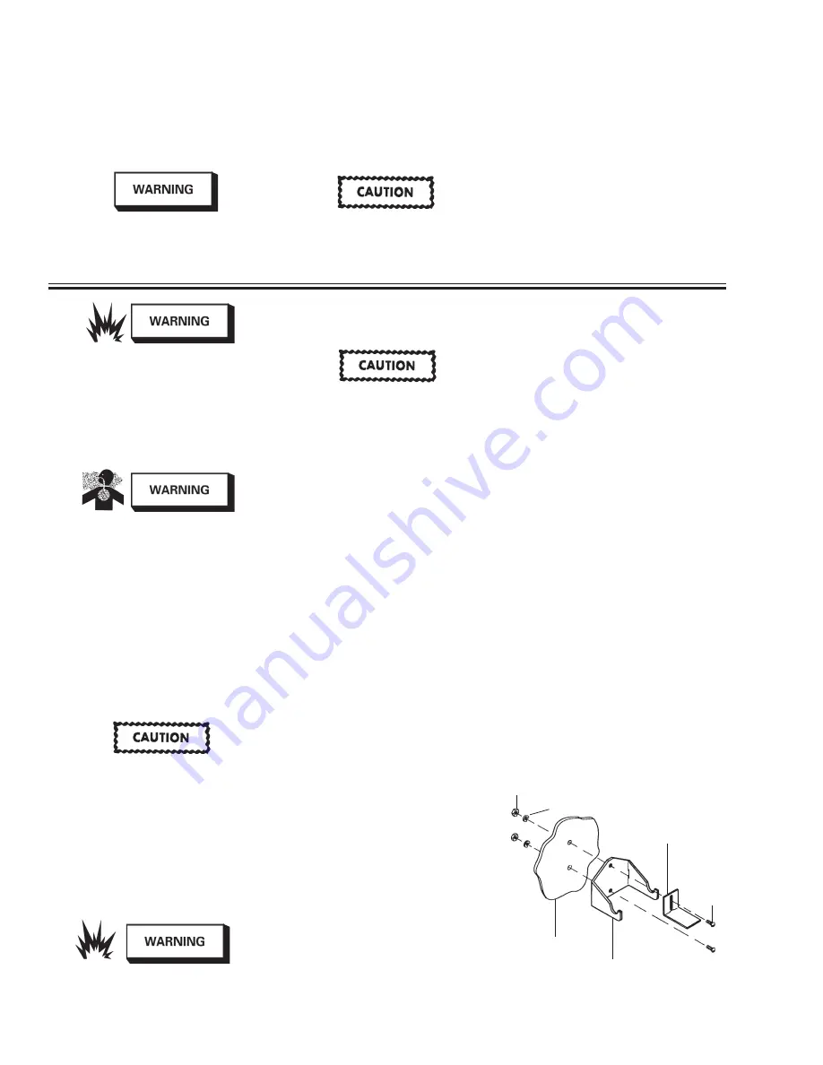
INSTALLATION – MOUNTING BRACKETS
1. Use the mounting bracket as a template
for locating the mounting holes.
2. Drill appropriate sized holes through
booth wall as shown in Figure 2. Two
5/16" round head screws, nuts and lock-
washers are supplied. If mounting into
a solid or hollow wall, use anchors (not
included).
3. Assemble mounting bracket to wall,
positioning “L” bracket with top screw.
4. Tighten bottom screw firmly. Leave top
screw partially loose so “L” bracket can
slide up out of the way.
5. Place filter in the bracket, positioning
between curved saddle ears. See Figure
1 on Page 1.
6. Slide “L” bracket down against top of
filter, then firmly tighten the top screw.
SAFETY PRECAUTIONS
This manual contains important information that all users must know and understand before using the equipment. This information
relates to USER SAFETY and PREVENTING EqUIPMENT PROBLEMS.
To help you recognize this information, we use the following terms to draw your attention to certain equipment labels and portions of
this manual. Please pay special attention to any label or information that is highlighted by one of these terms:
Note
Information that you should pay
special attention to.
Important information that tells
how to prevent damage to equip-
ment, or how to avoid a situation
that might cause minor injury.
Important information to alert
you to a situation that might cause
serious injury if instructions are not
followed.
INSTALLATION – AIR STATION
Risk of explosion and injury. Release
all air pressure from system before
servicing system. Be sure to read
and understand all Service Bulletins
on the separate components before
using the system. Use only specified
DeVilbiss parts.
Risk of equipment damage! Do not
install your air station where it is
subjected to sudden depressuriza-
tion cycles exceeding 20 PSIG. Quick
relieving air solenoid valves, typical
in some spray booths, will eventually
fail pressure gauges and filters.
To minimize sudden depressurization effect,
replace the existing solenoid with a "slow
closing solenoid valve". (One source: Auto-
matic Switch Co). Or, install an air adjusting
valve at the existing solenoid valve outlet.
For ease of installation and maintenance,
attach the assembled air station to the main
air line using a pipe union, (not included).
1. Be sure to read all Warnings and Cautions
in this manual and component manuals
on the unit before installation or using
this equipment.
2. Install air station system as close as pos-
sible to the point where the air is being
used. Use enclosed mounting bracket
to support Air Station.
3. Install main shut-off valve (supplied by
user) upstream of air drying system to
allow maintenance to the unit.
4. Install unit with air flow through filter in
direction of arrow on top of filters.
5. Minimum 3/4" NPT piping is recom-
mended. Avoid using fittings, couplings,
etc. that restrict air flow.
6. Maximum inlet pressure and operating
temperature is: 150 PSIG and 120° F
(48.9 C)
7. Three 6' lengths of vinyl tubing are
shipped loose with the system. Slide
over drains which protrude from bot-
tom of the filters. Place the other
end of vinyl tubing into appropriate
Figure 2 – Mounting Bracket
5/16" Nuts
5/16"
Rd. Hd.
Machine
Screws
“L” Bracket
5/16" Lockwashers
Booth Wall
Mounting Bracket
Risk of illness or death. Carbon mon-
oxide can cause nausea, fainting or
death. Stop using if carbon monoxide
is present. This unit does not remove
carbon monoxide. A carbon monox-
ide monitor should be incorporated
into your air supply line to warn of the
presence of carbon monoxide.
Risk of injury. Do not place unit in
service without metal bowl guard
installed. Filter units are sold only
with metal bowl guards. To minimize
the danger of flying fragments in the
event of plastic bowl failure, guard
must not be removed. If the unit is
in service without the metal bowl
guard installed, manufacturer’s war-
ranties are void and the manufacturer
assumes no responsibility for any
resulting loss. If unit has been in
service and does not have a metal
bowl guard, order one and install
before placing back in service.
Certain compressor oils, cleaning
agents and solvents may attack the
plastic and rubber components used
in the construction of this product.
This product should not be used in
conjunction with or in the vicinity
of these materials. Read and follow
material labels carefully. Please
consult DeVilbiss if in doubt.


