User Manual DEV 5072
Copyright DEV Systemtechnik GmbH 2016-2017
13
The grounding bolt is independent of the potential of the output terminals and
is connected to PE (Protective Earth) potential of the AC plugs as well as to the
ground (GND) potential of the data interface connectors.
Next, after the application of the DC output wiring, connect appropriate AC power
cables (chapter 2.3) to the AC plugs (
AC
1
…
AC
4
, IEC 60320-C20). Depending on the
number and on the location of the installed power supply modules, only the
corresponding AC power cables are to be connected.
Finally, make sure that all installed power supply modules of the DEV 5072 are
powered up sequentially (to minimize the switch-on surge) without the connected
load being turned on! If the power supply modules are powered up sequentially
with the connected load turned on, there is the risk of overloading already
activated power supply modules before the necessary number of activated power
supply modules is delivering the required power.
Note:
Due to the high power consumption of each power supply module, it is highly
recommended to use separately fused phases of the available AC mains.
The installation location of the power supply modules can be selected freely,
though it is recommended to install the power supply modules in the slot order
(as shown in the front view figure of chapter 3.2).
Make sure that the corresponding AC power cables are connected.
4.2.3
Installation and Exchange of Power Supply Modules
The DEV 5072 is delivered with the number of ordered power supply modules that
are already installed. Therefore, you may proceed in reading the next chapter.
In case that a power supply module has to be exchanged or that a DEV 5072 is to
be upgraded with an additional power supply module, the following instructions
are to be noticed. Please consider the related warnings stated in chapter 2.3.
Though the power supply modules are hot pluggable, it is recommended for
exchange operations either to power down the DEV 5072 or at least to deactivate
the corresponding power supply module via Web Interface (chapter 5.4.4.1) or via
SNMP (chapter 5.5.4.3.5.2).
D C
A C
H F E 2 5 0 0 -4 8 /S
D C
A C
H F E 2 5 0 0 -4 8 /S
D C
A C
H F E 2 5 0 0 -4 8 /S
To install an additional power supply module remove the blind plate covering the
desired slot in the first step.
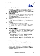
To remove -for instance- the first power supply module from the chassis, elevate
the module lock (indicated by the vertical green arrow in the figure above) and pull
the extraction handle (horizontal red arrows in the figure above) simultaneously.
Please check type and output voltage of the spare (or additional) power supply
module before the installation, since it has to be made sure that all power supply
modules in all slots are of the same type (please refer to the note in chapter 3.1.2
regarding the output voltage configuration of the DEV 5072 chassis).
Install the (replacement) power supply module by gently pushing it into the chassis
with the extraction handle closed. Lift the module lock during the last section of the
insertion process and make sure that the module is inserted deep enough (the


