User Manual DEV 5072
28
Copyright DEV Systemtechnik GmbH 2016-2017
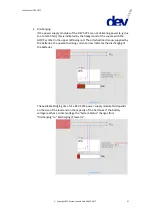
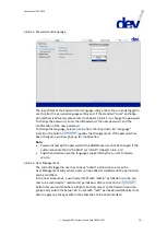
to adjust the "Current Alarm Level" to ~90% of the maximum possible current
capability. Note that after settings have been altered within this section in
Local Mode (!), a click on the
button is necessary to apply the
changes.
Note:
If the UPS functionality is activated (chapter 5.4.6.3.1), it is not possible to
adjust the "Voltage Setpoint" (as explained in chapter 4.3.1).
5.4.4.1
Power Supply Module
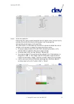
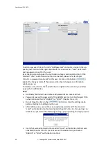
If on the left side of the Control Tab a power supply module is selected within the
structuring entry "
Power Modules
", the corresponding panel appears on the right side.
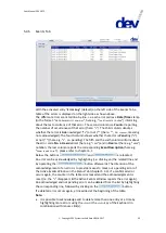
Within the "Status" section, some information on the selected power supply
module is shown: "Serial Number"; "Module Status" ("Enabled", "Disabled",
"Not present", "Wrong Voltage", or "Unsupported module type"); red, green, or
gray indicators for "AC Status", "DC Status", and "Fan Status"; and the display of
"Output Voltage", "Output Current", and "Temperature".
The "Surveillance Enable" check box is used e.g. to enable or to disable the
surveillance of a power supply module slot.
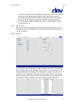
Clicking on the
button turns off the output of the selected power supply
module, e.g. to enable a safe removal of the module; please refer to chapter 4.2.3.
Note that if a power supply module is deactivated (i.e. the "Module Status" is
"Disabled", the "DC Status" is red, but the "AC Status" and the "Fan Status" are
green), the button is labeled
instead. The button is grayed out if the
device is in Remote Mode and/or if the "Module Status" of the related power
supply module is "Not present", "Wrong Voltage", or "Unsupported module type".
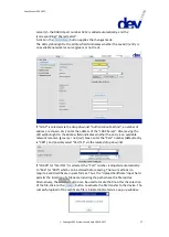
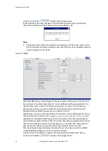
As stated in chapter 5.4.3 it is recommended to disable the surveillance of
unpopulated power supply module slots:


