background image

© 02/2010

OBJ_DOKU-21785-001.fm

2/2

6

Oil suction pipe

TCD 2013 2V

W 16-01-01

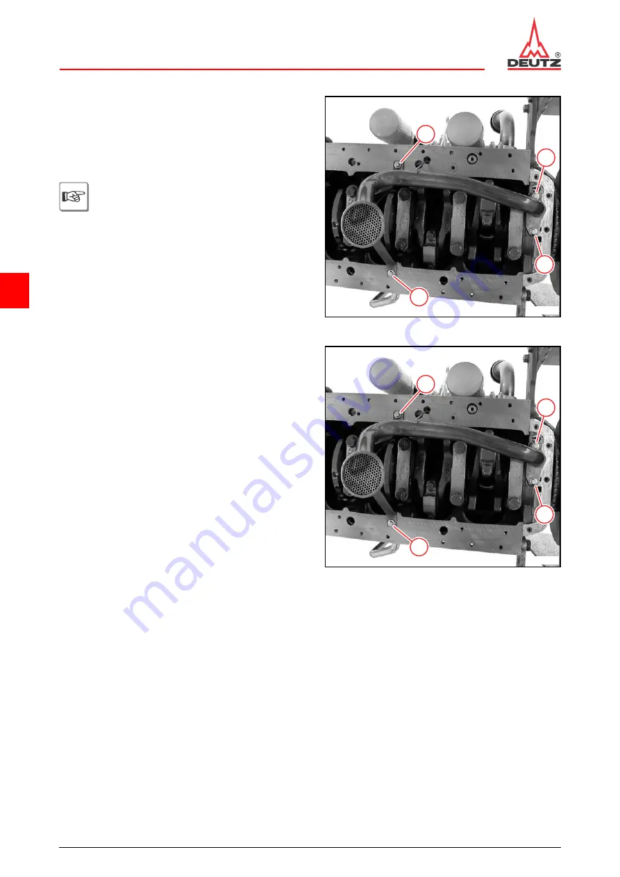
Installing the oil suction pipe

● Clean sealing surfaces.
● Mount new gasket.
● Mount oil suction pipe.
● Fasten screws.

Ensure that the installation location is free 

from faults.
Pay attention to different screw lengths.
M8 x 25 mm (1)
M8 x 20 mm (2)

2

1

1

2

© 44478-0

● Tighten screws (1).

22 Nm

● Install lubricating oil pan.

W 02-01-01

1

1

1

1

© 44479-0

Summary of Contents for TCD 2013 2V

Page 1: ...urther de velopment of the engines Reprinting and reproductions of any kind even in part require our written permission T h i s d o c u m e n t i s c o p y r i g h t p r o t e c t e d D i s t r i b u...

Page 2: ...0 221 822 0 Fax 49 0 221 822 3525 Internet www deutz com E Mail info deutz com Printed in Germany All rights reserved 1st Edition 02 2010 Order No 0312 2916 en Regarding copyright questions and licen...

Page 3: ...013 2V 0312 2916 en This document is subject to changes which may become necessary in the course of further de velopment of the engines Reprinting and reproductions of any kind even in part require ou...

Page 4: ...1 General 3 2 Specifications 3 3 Operating manual and workshop manual 3 4 Job cards 3 5 Explanation of symbols 4 Technical data 4 1 Testing and setting data 4 2 Tightening specifications 5 Job card ov...

Page 5: ...02 2010 OBJ_DOKU 21737 001 fm 2 2 DEUTZ engines Table of contents...

Page 6: ...1 05 2005 OBJ_DOKU 21738 001 fm 1 4 DEUTZ engines Foreword 1 Foreword...

Page 7: ...1 05 2005 OBJ_DOKU 21738 001 fm 2 4 DEUTZ engines Foreword...

Page 8: ...ance and repair is the availability of all the necessary equipment conventional and special tools and their perfect condition Engine parts such as springs clamps elastic re taining rings etc pose an i...

Page 9: ...1 05 2005 OBJ_DOKU 21738 001 fm 4 4 DEUTZ engines Foreword...

Page 10: ...2 11 2005 OBJ_DOKU 21739 001 fm 1 4 DEUTZ engines General 2 General...

Page 11: ...2 11 2005 OBJ_DOKU 21739 001 fm 2 4 DEUTZ engines General...

Page 12: ...e and care are the only way the engine can satisfy the demands you make on it Compli ance with the prescribed maintenance times and the careful execution of maintenance and care work are therefore ess...

Page 13: ...2 11 2005 OBJ_DOKU 21739 001 fm 4 4 DEUTZ engines General...

Page 14: ...3 02 2010 OBJ_DOKU 21740 001 fm 1 8 DEUTZ engines User notes 3 User notes...

Page 15: ...3 02 2010 OBJ_DOKU 21740 001 fm 2 8 DEUTZ engines User notes...

Page 16: ...operating and auxiliary materials be ing used Special protection measures are specified depend ing on the work being carried out and are identified in the job description Among other things it genera...

Page 17: ...t be pointed directly at them Electrical plug connections must be plugged when spraying Remove loose parts for example paint chips from assembly work with an industrial vacuum cleaner or other suction...

Page 18: ...are carried out The workshop floor is sealed or tiled No welding gear grinders general machine tools brakes or performance test benches may be operated in this room Regular cleaning of the workshop a...

Page 19: ...s repairs to the engine and compo nents for which more effort and appropriately quali fied technicians are required 3 4 Job cards The job cards are divided in the workshop manual into W and I job card...

Page 20: ...n lead to destruction of the component engine Must be observed Note General notes on assembly environmental protection etc No potential danger for man or machine Tool Conventional and special tools re...

Page 21: ...3 02 2010 OBJ_DOKU 21740 001 fm 8 8 DEUTZ engines User notes...

Page 22: ...4 02 2010 OBJ_DOKU 21741 001 fm 1 18 Technical data TCD 2013 2V Testing and setting data 4 Technical data 4 1 Testing and setting data...

Page 23: ...4 02 2010 OBJ_DOKU 21741 001 fm 2 18 Technical data TCD 2013 2V Testing and setting data...

Page 24: ...kness inlet TCD 2013 2V 2 62 mm P01 36 Valve edge thickness outlet TCD 2013 2V 2 3 mm P01 37 Valve head diameter inlet TCD 2013 2V 48 mm P01 38 Valve head diameter outlet TCD 2013 2V 42 mm Valve seat...

Page 25: ...nkshaft main bearing pin Underdimension stage TCD 2013 2V 0 25 mm P02 05 Limit for undermeasure step TCD 2013 2V 84 50 mm P02 06 Pin unroundness Wear limit TCD 2013 2V 0 01 mm P02 07 Crankshaft main b...

Page 26: ...a distance of 100 mm TCD 2013 2V 0 05 mm P02 43 Piston bolt liner inside diameter installed unmachined TCD 2013 2V 42 mm P02 45 Small end bush clearance between piston pin and small end bush TCD 2013...

Page 27: ...ation TOP in direction of combustion chamber TCD 2013 2V 1 5 2 0 mm P02 86 Joint clearance piston ring 3 Identification TOP in direction of combustion chamber TCD 2013 2V 0 3 0 6 mm P02 87 Axial clear...

Page 28: ...compression spring for the oil pressure control valve TCD 2013 2V 62 mm Cooling system P09 11 Coolant thermostat start of opening TCD 2013 2V 83 mm P09 13 Coolant thermostat stroke TCD 2013 2V at lea...

Page 29: ...ves Cylinder overlap 1 3 4 2 Set to 4 2 1 3 Valve overlap Outlet valve is not yet closed inlet valve begins opening The inlet valve opens briefly by 2 mm when the oulet valve is fully open This is not...

Page 30: ...4 02 2010 OBJ_DOKU 21741 001 fm 9 18 Technical data TCD 2013 2V Tightening specifications 4 2 Tightening specifications...

Page 31: ...4 02 2010 OBJ_DOKU 21741 001 fm 10 18 Technical data TCD 2013 2V Tightening specifications...

Page 32: ...90 10 9 M12x220 10 9 TCD 2013 2V 95 Nm Nut A00 005 Holder engine mounting on crankcase M16x40 10 9 M16x45 10 9 M16x75 10 9 M16x85 10 9 M16x110 10 9 M16x140 10 9 M16x155 10 9 M16x220 10 9 TCD 2013 2V 2...

Page 33: ...d in writing otherwi se use new screws every time they are loosened TCD 2013 2V 50 Nm 60 60 A02 020 Big end bearing cap on con rod Observe assembly specifica tion Use new screws every time they are lo...

Page 34: ...ar case M8x55 10 9 M8x60 10 9 TCD 2013 2V 21 Nm A04 025 Holder on gear case crankcase M8x80 10 9 TCD 2013 2V 30 Nm A05 011 Speed governor crankshaft front cover M6x12 Observe assembly specifica tion I...

Page 35: ...t 27 Nm A07 003 Injection lines on rail and pressure pipe nozzle High pressure pipe at high pressure pump Union nut Stage 1 Observe assembly specifica tion Use new pipe TCD 2013 2V 10 Nm A07 003 Injec...

Page 36: ...A08 001 Oil fillter interchangeable filter Oil gasket lightly TCD 2013 2V hand tight approx 10 Nm A08 015 Oil suction intake pipe holder on oil pump TCD 2013 2V 22 Nm A08 040 Lubricating oil pipe on e...

Page 37: ...09 046 Fan drive on fan console TCD 2013 2V 60 Nm A09 047 V rib disc on fan drive Stage 1 TCD 2013 2V 30 Nm A09 047 V rib disc on fan drive Stage 2 TCD 2013 2V 90 A09 048 Adapter on V belt pulley TCD...

Page 38: ...V 49 Nm A12 095 Pipe clip fastening M6 TCD 2013 2V 13 Nm Pipe clip for return pipe M8 20 Nm A13 001 Starter on crankcase gear case TCD 2013 2V 60 Nm A13 012 Generator on holder M8x75 TCD 2013 2V 30 Nm...

Page 39: ...gonal pole screw locked TCD 2013 2V 20 Nm A49 001 Connection piece on cylinder head clamping shoe TCD 2013 2V 25 Nm ID no Name Screw type Notes Remarks Series Pre tensio ning value Post clamping value...

Page 40: ...5 02 2010 OBJ_DOKU 21742 001 fm 1 12 Job card overview TCD 2013 2V Sorted alphabetically 5 Job card overview 5 1 Sorted alphabetically...

Page 41: ...5 02 2010 OBJ_DOKU 21742 001 fm 2 12 Job card overview TCD 2013 2V Sorted alphabetically...

Page 42: ...valve guide W 08 04 03 Cylinder head Checking the valve lag W 08 04 04 Cylinder head Checking the valves W 08 04 02 Cylinder head Disassembling assembling and checking the rocker arm and rocker arm br...

Page 43: ...ectrical equipment Removing and installing the fuel supply pump V belt drive W 20 02 01 Fuel pump Removing and installing the gearcase cover W 09 02 02 Gearcase Removing and installing the generator V...

Page 44: ...g the starter W 44 03 01 Starter Removing and installing the thermostat W 38 01 01 Thermostat housing Removing and installing the thermostat housing W 38 02 01 Thermostat housing Removing and installi...

Page 45: ...5 02 2010 OBJ_DOKU 21742 001 fm 6 12 Job card overview TCD 2013 2V Sorted alphabetically...

Page 46: ...5 02 2010 OBJ_DOKU 21742 001 fm 7 12 Job card overview TCD 2013 2V Sorted numerically 5 2 Sorted numerically...

Page 47: ...5 02 2010 OBJ_DOKU 21742 001 fm 8 12 Job card overview TCD 2013 2V Sorted numerically...

Page 48: ...add on W 05 02 01 Removing and installing torsional vibration damper V belt drive Torsional vibration damper W 05 03 01 Removing and installing the flywheel Flywheel W 05 05 01 Removing and installin...

Page 49: ...osition A High pressure pump W 17 01 05 Removing and installing the high pressure pump Installation position B High pressure pump W 19 01 01 Removing and installing the injector Injector W 20 01 01 Re...

Page 50: ...t W 48 02 03 Removing and installing the impulse transmitter camshaft Electrical equipment W 48 03 01 Removing and installing the pressure temperature sensor charge air Electrical equipment W 48 04 01...

Page 51: ...5 02 2010 OBJ_DOKU 21742 001 fm 12 12 Job card overview TCD 2013 2V Sorted numerically...

Page 52: ...6 11 2005 OBJ_DOKU 21743 001 fm 1 2 DEUTZ engines Job cards 6 Job cards...

Page 53: ...6 11 2005 OBJ_DOKU 21743 001 fm 2 2 DEUTZ engines Job cards...

Page 54: ...and installing the crankcase bleeding Standard tools Hose clip pliers 8011 Spring band pliers 9090 Removing the crankcase bleeding Loosen spring band clip 1 with spring band pliers Pull off bleeding...

Page 55: ...ip 2 Unscrew hollow screw 3 Remove sealing ring Loosen hose clip 4 Pull off oil return line 5 Remove bleed line 4 2 1 3 5 X X X 43944 0 Visually inspect the components 44132 0 Install crankcase bleedi...

Page 56: ...107 0 Mount the bleed line Plug in oil return line 5 Tighten hollow screw 3 29 Nm Position pipe clamp 2 Tighten screw 1 M8 30 Nm M6 13 Nm Fix the hose clip 4 with the hose clip pliers Use new sealing...

Page 57: ...02 2010 OBJ_DOKU 21744 001 fm 4 4 6 Crankcase TCD 2013 2V W 01 01 01...

Page 58: ...ssembly lever 9017 Special tools Assembly tool 142820 Self tapping screw Washer W 05 01 01 Removing the crankshaft sealing ring Remove the V belt V belt pulley W 05 01 01 Make a hole of approximately...

Page 59: ...m 2 6 6 Front cover TCD 2013 2V W 01 02 01 Pull out the crankshaft sealing ring with assembly le ver 44200 0 Visually inspect all running surfaces 44201 0 Installing the crankshaft sealing ring Remove...

Page 60: ...sure the clamping bushing 2 is in line with the bore 3 3 2 1 44203 0 Tighten screws 1 1 44204 0 Oil the sealing lip of the crankshaft sealing ring light ly Push the crankshaft sealing ring carefully...

Page 61: ...ation depth of crankshaft seal ing ring and select shim accordingly First assembly 2 shims 1 Repair installation depth 1 shim Maximum installation depth without washers 1 44206 0 Mount assembly sleeve...

Page 62: ...CD 2013 2V W 01 02 01 Tighten nut to the stop of the assembly sleeve 1 Remove assembly tool The crankshaft sealing ring is now at the pre selected installation depth 1 44209 0 Insert clamping bushing...

Page 63: ...02 2010 OBJ_DOKU 21745 001 fm 6 6 6 Front cover TCD 2013 2V W 01 02 01...

Page 64: ...d for series 2012 as an example The pro cedure for the other engines listed above is the same Installing the shaft sleeve Remove the crankshaft sealing ring W 01 02 01 39876 0 Visually inspect the cra...

Page 65: ...impact sleeve 1 lightly in the cen tre Knock on the shaft sleeve evenly all round The installation depth of the shaft sleeve is determined by the impact sleeve The shaft sleeve must cover the running...

Page 66: ...g the shaft sleeve Remove the crankshaft sealing ring W 01 02 01 Remove oil suction pipe W 16 01 01 39871 0 Unscrew screws 1 Remove front cover 1 1 1 1 1 44542 0 Place two mounting levers on the gate...

Page 67: ...02 02 Pull off the shaft sleeve Remove front cover 39874 0 Install front cover W 01 03 01 Install new shaft sleeve Installing the shaft sleeve Install oil suction pipe W 16 01 01 Install a new cranks...

Page 68: ...ls Feeler gauges Locking agent DEUTZ DW 72 W 01 02 01 W 05 01 01 W 16 01 01 Remove the front cover Remove V belt pulley W 05 01 01 Unscrew screws 1 Remove clamping strap 2 and fuel supply pump Unhook...

Page 69: ...3 2V W 01 03 01 Unscrew screws 1 Remove front cover 1 1 1 1 1 44542 0 Visually inspect the components 44543 0 Install front cover Knock out crankshaft sealing ring 1 Clean sealing surfaces Attention D...

Page 70: ...se Note installation position Make sure the clamping bushing 1 is in place 1 44545 0 Oil oil pump with lubricating oil 44546 0 Position the inner rotor on the crankshaft The countersinks on the cranks...

Page 71: ...flush with the oil tray sealing sur face Do not tighten screws 44548 0 Tighten the screws according to the tightening se quence Stage 1 3 Nm Stage 2 21 Nm 10 12 13 14 1 3 9 11 8 4 5 6 7 2 44550 0 Cut...

Page 72: ...Tighten screws 1 30 Nm Install crankshaft sealing ring opposite side to fly wheel W 01 02 01 Install V belt pulley W 05 01 01 1 44553 0 Mount holder with impulse transmitter Fasten screws Clean the th...

Page 73: ...smitter Press the impulse transmitter lightly against the feel er gauge blade 0 6 mm 44092 0 0 1 0 1 Press the impulse transmitter lightly against the feel er gauge blade Tighten screws arrows 20 Nm 4...

Page 74: ...the overhang of the cylinder liner Remove cylinder head W 08 03 01 Place shims 1 and measuring beam 2 on the seal ing surface of the crankcase Insert dial gauge into measuring beam Fix dial gauge wit...

Page 75: ...beam and spacing washers un til the stylus arrow is touching the sealing surface of the cylinder liner 0 03 0 08 mm Install cylinder head W 08 03 01 Make measurements at at least 3 other points on the...

Page 76: ...6 01 01 Collect leaking operating substances in suitable vessels and dispose of according to regulations Removing the pressure holding valve Remove oil suction pipe W 16 01 01 Pull out oil dipstick Dr...

Page 77: ...urn slide hammer into thread Pull out pressure holding valve Remove any drill shavings carefully 44572 0 Install pressure holding valve Apply locking agent to the collar of the new pressure holding va...

Page 78: ...02 2010 OBJ_DOKU 21749 001 fm 3 4 6 Crankcase TCD 2013 2V W 01 07 03 Knock in pressure holding valve to the stop with a suitable tool Install oil suction pipe W 16 01 01 Insert oil dipstick 44575 0...

Page 79: ...02 2010 OBJ_DOKU 21749 001 fm 4 4 6 Crankcase TCD 2013 2V W 01 07 03...

Page 80: ...moving and installing the piston cooling nozzles Standard tools W 05 05 01 Removing the piston cooling nozzles Remove crankshaft W 05 05 01 Screw self tapping screw 1 carefully into the piston cooling...

Page 81: ...6 Crankcase TCD 2013 2V W 01 08 01 Installing the piston cooling nozzles Clean the bores for the piston cooling nozzles in the crankcase Knock in new piston cooling nozzle 1 with pin to the stop Insta...

Page 82: ...ls Micrometer gauge Depth measuring appliance W 04 01 01 Checking the collar rest for the cylinder liner Remove cylinder liner W 04 01 01 Visually inspect collar rest arrow Visually inspect sealing su...

Page 83: ...02 2010 OBJ_DOKU 21751 001 fm 2 2 6 Crankcase TCD 2013 2V W 01 13 01...

Page 84: ...the crankcase Seal all openings Collect leaking operating substances in suitable vessels and dispose of according to regulations Emptying and filling the engine with opera ting media must be carried...

Page 85: ...Separation in the area of aluminium parts is not allowed Do not damage the sealing surfaces 1 2 45969 0 Drive in second separating tool 1 to the stop 2 Attention The tool can only be driven in in the...

Page 86: ...inspect the component 43450 1 Installing the lubricating oil pan Scrape off sealing compound with separating tool 46907 0 Clean the sealing surface on the crankcase with a wire brush Attention Wear p...

Page 87: ...he beading of the lube oil tray Apply the packing compound in an even bead thickness approx 3 5 mm The position of the packing compound is only partly illlustrated 43451 0 To align the lubricating oil...

Page 88: ...1 0 Tighten the screws according to the tightening se quence 30 Nm Representation Tightening sequence 6 cylinder 1 4 8 12 16 20 5 9 25 21 17 13 29 32 34 33 18 22 26 30 14 10 6 2 3 7 11 15 19 27 31 28...

Page 89: ...OKU 21752 001 fm 6 6 6 Lubricating oil sump TCD 2013 2V W 02 01 01 Insert new sealing ring Tighten screw plug 2 55 Nm M18x1 5 Insert oil dipstick 1 Fill in lubricating oil according to operating manua...

Page 90: ...W 06 01 01 Collect leaking operating substances in suitable vessels and dispose of according to regulations Lubricating oil and coolant must be filled according to the instructions in the opera ting...

Page 91: ...in the cylinder liner Attention Do not damage the running surfaces and the sealing surfaces 1 44442 0 Mount the counter holder 1 on the crankcase Do not mount the counter holders on the cylinder line...

Page 92: ...ylinder liner TCD 2013 2V W 04 01 01 Turn the nut 1 clockwise Remove the disassembly device 1 44064 0 Pull the cylinder liner up and out 44065 0 Remove O rings Visually inspect the components Testing...

Page 93: ...r cylinder liner W 01 13 01 Clean cylinder liner Insert new O rings 43568 0 Coat the crankcase and the cylinder liner in area X with lubricating oil X X 44441 0 Insert the cylinder liner in the crankc...

Page 94: ...ing to the diame ter of the cylinder liner and screw to the assembly le ver 1 43610 0 Fasten screw 2 Hook assembly lever 1 to screw Mount disc 3 on cylinder liner Ensure that the installation location...

Page 95: ...fm 6 6 6 Cylinder liner TCD 2013 2V W 04 01 01 Remove assembly lever Check the overhang of the cylinder liner W 01 05 01 44070 0 Mount liner holder 2 Tighten screws 1 Install piston and connecting ro...

Page 96: ...liner Remove cylinder head W 08 03 01 Check cylinder liner for visible signs of wear Remove piston and connecting rod W 06 01 01 44074 0 Prepare internal measuring device Mount probe bolt for the app...

Page 97: ...1 Insert internal measuring device in cylinder Balance the internal measuring device at the given measuring points and read off the measured value at the reversal point of the pointer Compare actual v...

Page 98: ...013 2V W 04 01 02 Measure collar height in area X with micrometer gauge 9 mm Measure collar height at several points X X X 48168 1 0 0 02 Install cylinder liner W 04 01 01 Install piston and connectin...

Page 99: ...02 2010 OBJ_DOKU 21754 001 fm 4 4 6 Cylinder liner TCD 2013 2V W 04 01 02...

Page 100: ...t tension measuring device 8115 Locking agent DEUTZ DW 72 Operation manual W 01 03 01 Attention Only test tighten renew V belts when the engine is not running The V belt tension of new V belts must be...

Page 101: ...OBJ_DOKU 21755 001 fm 2 12 6 V belt pulley add on TCD 2013 2V W 05 01 01 Loosen V belt by unscrewing the clamping screw 1 1 44039 0 Remove V belt 1 1 44040 0 Unscrew screws 1 Remove V belt pulley 2 2...

Page 102: ...21755 001 fm 3 12 6 V belt pulley add on TCD 2013 2V W 05 01 01 Loosen all screws arrow Do not unscrew screws 44526 0 Loosen screws 1 Swing the fuel supply pump 2 to the side arrow 1 2 44042 0 Remove...

Page 103: ...TCD 2013 2V W 05 01 01 Unscrew all screws arrow Remove the torsional vibration damper 44527 0 Unscrew screws arrows Remove adapter 1 Remove V belt pulley 2 Block flywheel with suitable tool 1 2 44528...

Page 104: ...nents 44530 0 Installing the V belt V belt pulley Make sure the clamping bushing arrow is in place Clean the threads of the screws and holes 44531 0 Fix the tooth lock washer with the largest hole 1 t...

Page 105: ...pulley add on TCD 2013 2V W 05 01 01 Tighten screws arrows 60 Nm Insert screw with locking agent 44533 0 Make sure the clamping bushings arrows are in place 44534 0 Mount V belt pulley The clamping b...

Page 106: ...tation angle disc Stage 1 30 Nm Stage 2 60 Stage 3 60 Attention Renew screws every time they are loo sened Block flywheel with suitable tool 1 1 44537 0 Mount the torsional vibration damper Tighten th...

Page 107: ...01 01 Mount V belt 1 for coolant pump 1 44043 0 Press clamping strap 1 in direction of arrow with a suitable tool Tighten screw 2 30 Nm 1 2 44049 0 Check V belt tension with V belt tension measuring...

Page 108: ...uides arrow 44050 0 Press the V belt measuring device against the V belt with the button 1 until you hear it click Read measured value at the intersection arrow of the indicator arm and scale Operatio...

Page 109: ...21755 001 fm 10 12 6 V belt pulley add on TCD 2013 2V W 05 01 01 Mount V belt pulley 2 Tighten screws 1 2 1 44041 0 Mount V belt 1 for generator 1 44040 0 Tighten V belt 1 by turning the clamping scr...

Page 110: ...ng device on V belt The V belt must be between the guides arrow 44054 0 Press the V belt measuring device against the V belt with the button 1 until you hear it click Read measured value at the inters...

Page 111: ...3 2 1 44056 0 Tighten screws arrows 30 Nm 44057 0 Set gap dimension for impulse transmitter crankshaft Check gap dimension with feeler gauge blade 0 6 mm Set gap dimension for speed governor cranksha...

Page 112: ...ually inspect the components 1 1 1 44436 0 Installing the torsional vibration damper Mount the torsional vibration damper M10x20 12 9 without washer Tighten screws alternately 70 Nm Note installation...

Page 113: ...02 2010 OBJ_DOKU 21756 001 fm 2 2 6 Torsional vibration damper TCD 2013 2V W 05 02 01...

Page 114: ...05 03 01 Removing and installing the flywheel Standard tools Rotation angle disc 8190 Guide pin self const ructed Removing the flywheel Unscrew all screws arrow Remove flywheel Block flywheel with su...

Page 115: ...ing the flywheel Insert clamping bushing 1 1 44555 0 Insert self made guide pin arrow Mount flywheel For example a pin bolt The bores in the flywheel must match the threaded bores in the crankshaft fl...

Page 116: ...M10x35 M10x85 Tighten screws Stage 1 30 Nm Stage 2 60 Stage 3 60 Block flywheel with suitable tool 42826 0 M10x30 Tighten screws Stage 1 30 Nm Stage 2 60 Stage 3 30 Block flywheel with suitable tool 4...

Page 117: ...02 2010 OBJ_DOKU 21757 001 fm 4 4 6 Flywheel TCD 2013 2V W 05 03 01...

Page 118: ...the crankshaft Standard tools Socket wrench insert 8035 Special tools Turn over gear 100380 W 01 03 01 W 05 05 03 W 09 02 02 Removing crankshaft Remove front cover opposite side to flywheel W 01 03 0...

Page 119: ...screws 2 2 1 44222 0 Place lifting journal of the respective cylinder at bot tom dead centre BDC Attention Do not jam the con rods when turning the crankshaft 44223 0 Unscrew screws 1 Remove big end...

Page 120: ...mshaft 1 3 2 44225 0 Turn the crankshaft evenly until the marking 1 on the crankshaft flange is in line with your mark 2 on the camshaft gear wheel The marking on the camshaft gear wheel is covered by...

Page 121: ...order in which they should be installed Note order of cylinders 1 2 44228 0 Press the con rods carefully out of the lifting journal Lift out the crankshaft 44230 0 Remove both thrust ring halves arro...

Page 122: ...Note the assignment of the bearing shells The anti rotation lock 1 must lock in groove 2 1 2 44232 0 Insert lower main bearing shells in the respective main bearing cover Note the assignment of the b...

Page 123: ...he assignment of the bearing shells The anti rotation lock 1 must lock in groove 2 1 2 44235 0 Insert bearing shell in the respective big end bearing cap Note the assignment of the bearing shells The...

Page 124: ...cing the cylinder head 1 44237 0 Insert the crankshaft carefully in the crankcase Set the crankshaft in line with the camshaft Attention Do not jam the con rods when inserting the crankshaft Make sure...

Page 125: ...ws 1 2 42662 0 Fix both thrust ring halves with a little grease to the bearing cap Bearing cap with identification 2 Use thrust ring halves with guide lug arrow Oil grooves 1 face the crankshaft web f...

Page 126: ...age 3 60 Attention Screws can be used a maximum 3 times with written documentation Use socket wrench insert 1 44241 0 Installing the big end bearing cap Pull con rods carefully on to the lifting journ...

Page 127: ...of the big end bearing cap The identification numbers 1 on the con rod and the big end bearing cap must be identical and opposite to each other when assembled 2 6 5 1 9 2 6 5 1 9 1 44244 0 Tighten ne...

Page 128: ...TCD 2013 2V W 05 05 01 Insert oil dipstick 1 1 44221 0 Check axial backlash of crankshaft crankshaft in stalled W 05 05 03 44187 0 Install the gear case cover flywheel side W 09 02 02 Install front c...

Page 129: ...02 2010 OBJ_DOKU 21758 001 fm 12 12 6 Crankshaft TCD 2013 2V W 05 05 01...

Page 130: ...haft Standard tools Magnetic measuring stand Micrometer gauge Internal measuring device Prisms Hardness tester Special tools Dial gauge 100400 W 05 05 01 Checking the bearing pin hardness Remove crank...

Page 131: ...wn briefly strikes the sur face and jumps up to the measured value 2 1 44445 0 Read off displayed value arrow from hardness test er 53 HRC The measured value is to be converted according to the table...

Page 132: ...e diameter of the lifting journals Measure lifting journal with micrometer gauge Standard 68 00 mm Measuring points see diagram 42604 0 0 0 02 Checking the rotation Mount magnetic measuring stand Inse...

Page 133: ...aces of the micrometer gauge and set the dial gauge at the reversal point of the pointer to 0 35825 2 Measure bearing width with internal measuring de vice between thelay on surfaces of the thrust rin...

Page 134: ...03 01 W 05 05 01 W 09 02 02 Remove front cover W 01 03 01 Remove the gear case cover W 09 02 02 Mount magnetic measuring stand Insert dial gauge Apply stylus to the crankshaft end with pre tension Pr...

Page 135: ...ing cap 2 Remove lower bearing shell Remove both thrust ring halves arrows Use socket wrench insert 1 2 1 44181 0 Remove both thrust ring halves arrows 44182 0 Measure the wall thickness of the thrust...

Page 136: ...gauge to 38 mm Push the internal measuring device between the test surfaces of the micrometer gauge and set to 0 35825 2 Measure locating bearing width Note measured value dimension a 42606 0 Place th...

Page 137: ...sh Given Measured a 38 6 mm b 38 4 mm Calculation Dimension a Dimension b Result 0 2 mm 35827 2 Make sure the clamping bushings 1 are in place 1 44183 0 Install upper thrust ring halves according to m...

Page 138: ...st ring halves according to mea sured axial clearance Bearing cap with identification 2 The oil grooves 1 face the crankshaft web face 1 2 42663 0 Insert bearing cap 1 The gate arrow on the bearing ca...

Page 139: ...0 001 fm 6 6 6 Crankshaft TCD 2013 2V W 05 05 03 Check axial backlash of crankshaft 0 1 0 3 mm Remove magnetic measuring stand Remove dial gauge Install front cover W 01 03 01 Install the gear case co...

Page 140: ...s it is If con rod and big end bearing cover are assembled the wrong way around the con rod will be unusable Do not damage the fracture surfaces of the con rod and big end bearing cover Collect leakin...

Page 141: ...s 1 Remove big end bearing cap 2 Remove bearing shell Lay out components in the order in which they should be installed Note order of cylinders 1 2 44248 0 Press out the piston and connection rod Lay...

Page 142: ...Visually inspect the components 44251 0 Completing con rod and piston Insert new locking ring Ensure that the installation location is free from faults 44252 0 Insert con rod The flywheel crankshaft...

Page 143: ...through Insert new locking ring Ensure that the installation location is free from faults 44254 0 Installing the piston and con rod Make sure the clamping bushings 1 are in place 1 44211 0 Insert bear...

Page 144: ...nti rotation lock 1 must lock in groove 2 2 1 44216 0 Arrange the piston ring joints with an offset of about 120 to each other Check piston rings and piston ring grooves W 07 02 02 42380 1 Lightly oil...

Page 145: ...bol flywheel crankshaft 1 must face the flywheel The piston ring compressor must lie flat on the cylinder liner 1 44256 0 Press the con rod carefully against the lifting journal Attention Do not jam t...

Page 146: ...13 2V W 06 01 01 Tighten new screws with rotation angle disc Stage 1 30 Nm Stage 2 60 Stage 3 60 44259 0 Insert oil dipstick Unscrew screws 1 Remove the liner holder 2 1 1 2 44260 0 Install oil suctio...

Page 147: ...02 2010 OBJ_DOKU 21761 001 fm 8 8 6 Connecting rod TCD 2013 2V W 06 01 01...

Page 148: ...internal measuring device Mount probe bolt for the appropriate measuring range in the internal measuring device Mount dial gauge with approx 1 mm pre tension in the internal measuring device Set micro...

Page 149: ...rance 34770 2 0 05 0 04 Checking diameter of the piston bolt Measure piston pin with micrometer gauge 42 mm Note the measured value dimension B The dimension B is required to determine the piston bolt...

Page 150: ...Mount big end bearing cap Attention Note the assignment of the big end bearing cap The identification numbers 1 on the con rod and the big end bearing cap must be identical and opposite to each other...

Page 151: ...measuring device between the test surfaces of the micrometer gauge and set the dial gauge at the reversal point of the pointer to 0 36094 1 Diagram for measuring the con rod bearing bore at the points...

Page 152: ...er Make sure the clamping bushings 1 are in place 1 44440 0 Insert bearing shell in the con rod Attention Note the assignment of the bearing shells The anti rotation lock 1 must lock in groove 2 1 2 4...

Page 153: ...7 0 Tighten screws alternately with rotation angle disc and socket wrench insert Stage 1 50 Nm Stage 2 60 Stage 3 60 44218 0 Prepare internal measuring device Mount probe bolt for the appropriate meas...

Page 154: ...and read off the measured value at the reversal point of the pointer 72 5 mm Note the measured value dimension C When the wear limit is reached the con rod must be replaced 44219 0 0 02 0 Checking the...

Page 155: ...ove test fork in direction of arrow Check that the con rod is parallel Permissible deviation from A to B 0 05 mm Attention Aligning the con rod is not permissible Distance between A and B 100 mm B A 3...

Page 156: ...ng the piston bolt bore Remove piston from con rod W 06 01 01 44262 0 Prepare internal measuring device Mount probe bolt for the appropriate measuring range in the internal measuring device Mount dial...

Page 157: ...the internal measuring device at the given measuring points and read off the measured value at the reversal point of the pointer 42 mm See schematic diagram for measuring points 43483 0 0 017 0 010 C...

Page 158: ...CD 2013 2V W 07 01 02 Measure piston diameter with micrometer gauge Measuring point 1 107 700 mm Measuring point 2 107 800 mm Measuring point 3 107 660 mm Assemble con rod and piston W 06 01 01 See sc...

Page 159: ...02 2010 OBJ_DOKU 21763 001 fm 4 4 6 Piston TCD 2013 2V W 07 01 02...

Page 160: ...piston ring pliers 130300 Trapezoidal groove wear gauge 130420 W 06 01 01 Checking the piston rings and piston ring grooves Remove piston from con rod W 06 01 01 Set universal piston ring pliers to t...

Page 161: ...groove for first piston ring with trapezoidal groove wear gauge 33866 2 If there is a gap S between the trapezo idal groove wear gauge and piston the pis ton can be used again S 33867 2 If the trapezo...

Page 162: ...holder 2 1 1 2 44260 0 Insert the piston ring 1 in the cylinder Align the piston ring in the cylinder by pushing the piston 1 44265 0 Measure the piston ring joint clearance with a feeler gauge 1 pis...

Page 163: ...label faces the combustion chamber 1 2 3 44267 0 Install piston rings with universal piston ring pliers Set spring joint of the bevelland edge oil control ring 180 to the ring joint 44268 0 Checking t...

Page 164: ...02 2010 OBJ_DOKU 21764 001 fm 5 6 6 Piston TCD 2013 2V W 07 02 02 Assemble con rod and piston W 06 01 01 44270 0...

Page 165: ...02 2010 OBJ_DOKU 21764 001 fm 6 6 6 Piston TCD 2013 2V W 07 02 02...

Page 166: ...or 100190 W 11 01 01 W 19 01 01 Checking the compression pressure Setting the valve clearance with exhaust return module installed W 11 01 01 Remove injector W 19 01 01 Insert connector 1 Use sealing...

Page 167: ...the altitude of the engine installation site Therefore limit values cannot be determined exactly The compression pressure measurement is only recommended as a reference measu rement of all cylinders o...

Page 168: ...5 001 fm 3 4 6 Cylinder head TCD 2013 2V W 08 00 01 Remove the compression pressure tester 44103 0 Unscrew screw 1 Remove clamping shoe 2 Remove connector Remove sealing ring Installing the injector W...

Page 169: ...hnical Data Tightening specifications ID no Name Screw type Notes Remark Value A49 001 Connection piece on cylinder head clamping shoe 25 Nm For the tightening procedure according to torque using a to...

Page 170: ...2V W 08 01 01 Removing and installing the cylinder head cover Standard tools Spring band pliers 9090 Removing cylinder head Loosen spring band clip 1 with spring band pliers Pull off bleeding hose 2...

Page 171: ...08 01 01 Unscrew all screws Remove cylinder head cover and gasket 44127 0 Installing cylinder head cover Clean sealing surfaces Insert new gasket arrow 44128 0 Mount cylinder head cover Tighten screws...

Page 172: ...OBJ_DOKU 21766 001 fm 3 4 6 Cylinder head TCD 2013 2V W 08 01 01 Mount cover 2 Tighten screws 1 8 5 Nm 2 1 44126 0 Plug on bleeding hose Position the spring band clip 1 with the spring band pliers 1...

Page 173: ...tions ID no Name Screw type Notes Remark Value A01 004 Cylinder head cowling on cylinder head M6 13 Nm A13 041 Cover plate on cylinder head cover M6x16 self tapping 8 5 Nm For the tightening procedure...

Page 174: ...the cylinder head hood W 08 01 01 Unscrew screws 1 Pull the exhaust return module 2 off the plug ele ment in the direction of the arrow Remove exhaust return module 2 Loosen screws evenly to avoid jam...

Page 175: ...pect the components 44099 0 Installing the exhaust return module Setting the valve clearance with or without removal of exhaust return module W 11 01 01 Pull out plug element 1 1 42927 0 Insert new O...

Page 176: ...different screw lengths Screws M8 x 55 mm 2 Screws M8 x 120 mm 3 1 2 44108 1 Retighten the screws 1 2 and 3 in the tightening order Stage 1 10 Nm Stage 2 30 Nm 2 3 1 X X X 44109 0 Push exhaust return...

Page 177: ...1 fm 4 6 6 Cylinder head TCD 2013 2V W 08 02 01 Retighten the screws 1 2 and 3 in the tightening order Stage 1 10 Nm Stage 2 30 Nm Set the control piston clearance W 11 01 01 Mount cylinder head cover...

Page 178: ...emark Value A01 011 Exhaust gas return module on rocker arm bracket Stage 1 Observe tightening sequence 10 Nm A01 011 Exhaust gas return module on rocker arm bracket Stage 2 Observe tightening sequenc...

Page 179: ...02 2010 OBJ_DOKU 21767 001 fm 6 6 6 Cylinder head TCD 2013 2V W 08 02 01...

Page 180: ...exhaust gas return Standard tools W 01 01 01 Collect leaking operating substances in suitable vessels and dispose of according to regulations Removing the solenoid valve exhaust return line Removing t...

Page 181: ...ect the components 44419 0 Installing the solenoid valve exhaust return line Clean sealing surfaces Mount new O ring 1 Insert new O ring 2 Oil O rings lightly Observe the order of installation of the...

Page 182: ...02 2010 OBJ_DOKU 21768 001 fm 3 4 6 Cylinder head TCD 2013 2V W 08 02 02 Plug in the cable plug 1 Install crankcase breather W 01 01 01 Ensure that the connection is perfect 1 44417 0...

Page 183: ...02 2010 OBJ_DOKU 21768 001 fm 4 4 6 Cylinder head TCD 2013 2V W 08 02 02...

Page 184: ...01 01 W 44 02 01 W 49 02 01 Removing the cylinder head Attach turning gear W 49 02 01 Remove generator W 44 02 01 Unscrew screw 1 Remove clamping strap 2 Remove thermostat housing W 38 02 01 Remove th...

Page 185: ...head TCD 2013 2V W 08 03 01 Unlock cable plug 1 and remove Unlock cable plug 2 and remove 1 2 44144 0 Unscrew hollow screw 1 Remove sealing rings Remove fuel return line 2 Hold connection piece 3 2 3...

Page 186: ...eam 1 and workshop crane Lift the cylinder head carefully from the crankcase Align chains parallel to the cross beam 1 44147 0 Remove the cylinder head gasket Clean sealing surfaces 44148 0 Installing...

Page 187: ...head gasket 1 42 mm 2 hole cylinder head gasket 1 52 mm 3 hole cylinder head gasket 1 62 mm Example Piston projection 0 7 mm cor responds to cylinder head gasket with 3 holes arrow 44154 0 Make sure...

Page 188: ...er head screws can be used max 3 times with written proof otherwise renew every time they are loosened 44157 0 Tighten all cylinder head screws according to the tightening sequence Stage 1 50 Nm Stage...

Page 189: ...temperature transmitter Plug cable plug 2 into the solenoid valve exhaust gas return line Ensure that the connection is perfect 2 1 44160 0 Installing the injector W 19 01 01 Mount cylinder head cover...

Page 190: ...ad TCD 2013 2V W 08 03 01 Install the charge air pipe W 22 01 01 Install the exhaust pipe W 41 01 01 Install thermostat housing W 38 02 01 Mount clamping strap 2 Fasten screw 1 Install generator W 44...

Page 191: ...02 2010 OBJ_DOKU 21769 001 fm 8 8 6 Cylinder head TCD 2013 2V W 08 03 01...

Page 192: ...the crankshaft until the respective piston is just in front of the top dead centre arrow Keep the cylinder liner pressed down to the stop 44150 0 Insert dial gauge into measuring beam Place shims 1 a...

Page 193: ...uge to 0 44152 0 Measuring points see diagram Measuring points 1 and 2 2 1 34151 2 Move the measuring beam Apply stylus to the specified measuring points under pre tension Note the largest measured va...

Page 194: ...ools Slide gauge Assembly lever 9017 Special tools Support bracket 120900 Base plate 120910 W 08 03 01 Removing the valves Remove cylinder head W 08 03 01 Mount support bracket 1 on base plate 2 Mount...

Page 195: ...04 01 Remove thrust washer 1 1 44165 0 Install assembly lever 1 Press down valve spring with assembly lever Remove both tapper collets 2 Remove valve spring plates valve springs and valves Remove asse...

Page 196: ...isually inspect the components 44168 0 Installing the valves Measure valve spring length with slide gauge 64 7 mm When the wear limit is reached the valve spring must be renewed 35856 2 Oil the new va...

Page 197: ...damage or press out the valve stem seal when inserting the valve 44170 0 Insert valve spring 1 Insert valve spring plate 2 The closely wound end of the valve plate faces the cylinder head 2 1 44171 0...

Page 198: ...thrust washer 1 Ensure that the installation location is free from faults 1 44165 0 Insert snap ring arrow Ensure that the installation location is free from faults 44173 0 Remove cylinder head from s...

Page 199: ...02 2010 OBJ_DOKU 21771 001 fm 6 6 6 Cylinder head TCD 2013 2V W 08 04 01...

Page 200: ...valves When the wear limit is reached the valve must be renewed Checking valve stem diameter Remove valves W 08 04 01 Measure valve stem diameter with micrometer gauge Inlet valve 8 98 mm Exhaust val...

Page 201: ...21772 001 fm 2 2 6 Cylinder head TCD 2013 2V W 08 04 02 Checking valve head diameter Measure valve head diameter with slide gauge Inlet valve 48 mm Exhaust valve 42 mm Install valves W 08 04 01 42184...

Page 202: ...W 08 04 01 New valves are used for testing When the wear limit is reached the valve guide must be renewed Checking the valve guide Remove valves and valve shaft seals W 08 04 01 Visually inspect valve...

Page 203: ...ove valve back and forth in direction of arrow Inlet valve 0 045 0 075 mm Exhaust valve 0 065 0 095 mm The valve stem ends must be flush with the valve guide The whole rocker path must be taken into c...

Page 204: ...appliance Special tools Support bracket 120900 Base plate 120910 W 08 03 01 Attention When the wear limit is reached the valve seat insert and or valve must be renewed Checking the valve lag Mount su...

Page 205: ...valve lag from the centre of the valve head to the cylinder head sealing surface Inlet valve 0 99 mm Exhaust valve 1 mm 42598 0 0 1 0 1 0 15 0 1 Remove cylinder head from support bracket 1 1 44177 0 R...

Page 206: ...ssembly lever 9017 Special tools Assembly tool 142810 Self tapping screw Washer W 05 03 01 Removing the crankshaft sealing ring Remove flywheel W 05 03 01 Make a hole of approximately 3 mm in the cran...

Page 207: ...l out the crankshaft sealing ring with assembly le ver 44190 0 Visually inspect all running surfaces 44191 0 Install crankshaft sealing ring Mount guide sleeve 1 Tighten screws The bores in the guide...

Page 208: ...e sleeve Use new crankshaft sealing ring The sealing lip faces the crankcase 44193 0 Mount shims 1 Pay attention to installation depth of crankshaft seal ing ring and select shim accordingly First ass...

Page 209: ...2013 2V W 09 01 01 Plug in the bearing 1 Screw on nut 2 2 1 44196 0 Tighten nut to the stop of the assembly sleeve 1 Remove assembly tool Install flywheel W 05 03 01 The crankshaft sealing ring is now...

Page 210: ...cking compound DEUTZ DW 48 W 02 01 01 W 05 03 01 W 09 01 01 W 44 03 01 W 48 02 03 W 52 01 01 Removing the gearcase Unlock cable plug 1 and remove Unlock cable plug 2 and remove Remove cable tie arrows...

Page 211: ...02 02 Unlock central plug 1 arrow and pull off from hold er Remove connection housing W 52 01 01 Remove flywheel W 05 03 01 Remove lubricating oil pan W 02 01 01 1 44450 0 Unscrew screws 1 Remove the...

Page 212: ...02 2010 OBJ_DOKU 21776 001 fm 3 10 6 Gearcase TCD 2013 2V W 09 02 02 Unscrew screws 1 Remove cover 2 1 2 1 44453 0 Unscrew screws 1 1 1 1 44454 0 Unscrew screws 1 Remove gearcase cover 1 1 1 44455 0...

Page 213: ...2 Visually inspect the component 44456 0 Installing the gearcase cover Knock out crankshaft sealing ring 1 Attention Do not damage sealing surface when knocking out 1 44457 0 Clean sealing surfaces Th...

Page 214: ...hour at most Use packing compound DEUTZ DW 67 Sealing bead thickness approx 1 4 mm 44458 0 Align gearcase cover Mount gearcase cover Tighten screws 1 Do not move the gearcase cover after mounting Do n...

Page 215: ...face arrows The oil tray sealing surface on the crankcase must face downwards 44461 0 Tighten the screws according to the tightening se quence Tighten scews 1 and 2 M16x60 70 Nm Tighten scews 3 to 14...

Page 216: ...ng surfaces must be dry and free from grease and dirt Use packing compound DEUTZ DW 48 Sealing bead thickness approx 1 5 mm 44462 0 Mount cap 1 Tighten screws 2 Note the installation position of the c...

Page 217: ...2V W 09 02 02 Press in the cap 1 to the stop Tighten screws 2 Use M8 x 60 mm screws Do not tighten screws 2 1 2 44464 0 Mount holder 1 Tighten screws 2 Use M8 x 55 mm screws Do not tighten screws 2 1...

Page 218: ...ernately 20 Nm 1 44593 0 Install new crankshaft sealing ring flywheel side W 09 01 01 Install connection housing W 52 01 01 Install flywheel W 05 03 01 Install starter W 44 03 01 Install lubricating o...

Page 219: ...09 02 02 Lay cable harness and fix with cable ties arrows 44449 0 Plug in the cable plug 1 Plug in the cable plug 2 Lay cable harness and fix with cable ties arrows Install impulse transmitter camshaf...

Page 220: ...01 04 W 17 01 05 Removing the camshaft Remove high pressure pump and roller tappet in stallation position A W 17 01 04 Remove high pressure pump and roller tappet in stallation position B W 17 01 05 R...

Page 221: ...TCD 2013 2V W 10 02 01 Remove clamping bracket 1 from the adapter plates 2 1 1 2 2 44472 0 Push away the assembly block on the flywheel side 44473 0 Press in all tappets Pull out the camshaft 1 caref...

Page 222: ...out components in the order in which they should be installed Note order of cylinders 42711 0 Installing tappets Oil all tappets arrow lightly Insert all tappets Note assignment 42711 0 Installing th...

Page 223: ...oards 2 90 Nm 1 1 2 2 44472 0 Unhook the crankcase from the workshop crane Unscrew screws 1 1 1 44471 0 Install crankshaft W 05 05 01 Install rocker arms and rocker arm brackets W 11 02 01 Install hig...

Page 224: ...02 02 Checking the camshaft Standard tools Micrometer gauge W 10 02 01 Checking the camshaft Remove camshaft W 10 02 01 Visually inspect cams and bearing pins for wear 42713 0 Diagram for measuring th...

Page 225: ...g the diameter of the journal Measure the bearing pin 64 2 mm See schematic diagram for measuring points When the limit value is reached the cams haft must be replaced 42714 0 0 2 0 2 Check camshaft g...

Page 226: ...valve clearance Engine oil temperature 80 C In engines without an exhaust return module a slotted setting screw must be installed in place of a hexagon socket head screw Setting engine to valve overla...

Page 227: ...t closed inlet valve begins to open When the inlet valve is fully open the out let valve opens briefly approx 2 mm This is not the valve overlap 00000 0 Valve overlap means The inlet valve starts open...

Page 228: ...ocker arm must touch the thrust washer of the spring cap arrow 1 2 X X X 44113 0 Set the rotation angle disc with a socket wrench in sert at the adjusting screw Fix magnet of rotation angle disc on cy...

Page 229: ...ve clearance Loosen lock nut 1 Press in the adjusting screw 2 to the stop The rocker arm must touch the thrust washer of the spring cap arrow 2 1 44117 0 Set the rotation angle disc on the adjusting s...

Page 230: ...tting screw 150 in direction of arrow 150 X X X 44119 0 Hold adjusting screw Tighten locking nut arrow with box spanner 20 Nm Remove rotation angle disc Set all other valves see page 1 4 cylinders 2 6...

Page 231: ...ce inlet with rotary angle disc 90 P01 62 Valve clearance outlet with rotary angle disc 150 ID no Name Screw type Notes Remark Value A01 003 Locking nut valve clearance setting screw 20 Nm A01 012 Loc...

Page 232: ...earance Engine oil temperature 80 C The control piston clearance of the exhaust return line must be set after setting the valve clearance Setting engine to valve overlap Remove the cylinder head hood...

Page 233: ...t valve is not yet closed inlet valve begins to open When the inlet valve is fully open the out let valve opens briefly approx 2 mm This is not the valve overlap Valve overlap means The inlet valve st...

Page 234: ...The rocker arm must touch the thrust washer of the spring cap arrow 1 2 43042 0 Set the rotation angle disc on the adjusting screw with the crowfoot wrench Fix magnet of rotation angle disc on cylinde...

Page 235: ...ve clearance Loosen lock nut 1 Press in the adjusting screw 2 to the stop The rocker arm must touch the thrust washer of the spring cap arrow 1 2 43046 0 Set the rotation angle disc on the adjusting s...

Page 236: ...ction of arrow 150 43048 0 Hold adjusting screw Tighten locking nut arrow with box spanner 20 Nm Remove rotation angle disc Set all other valves see page 1 4 cylinder 2 6 cylinder 43049 0 Setting the...

Page 237: ...er 2 6 cylinder X X X 44110 0 Loosen lock nut 1 Press in the adjusting screw 2 to the stop The rocker arm must touch the thrust washer of the spring cap arrow 2 1 44122 0 Set the rotation angle disc o...

Page 238: ...ting screw 144 in direction of arrow 144 44124 0 Hold adjusting screw Tighten locking nut arrow with box spanner 20 Nm Remove rotation angle disc Set all other control pistons see page 1 4 cylinder 2...

Page 239: ...Valve clearance outlet with rotary angle disc 150 P01 64 Clearance between control piston and rocker arm with rotary angle disc 144 ID no Name Screw type Notes Remark Value A01 003 Locking nut valve...

Page 240: ...9 02 01 Removing the rocker arm and rocker arm bracket Attach turning gear W 49 02 01 Remove exhaust gas return module W 08 02 01 Unscrew screws 1 Remove rocker arm brackets 2 Lay out components in th...

Page 241: ...ts 44133 0 Installing the rocker arm and rocker arm bracket Insert stop rods 1 Note the assignment of the stop rods The stop rod must be seated with the ball head in the ladle of the tappet 1 43949 0...

Page 242: ...n the rocker arm bracket must be in line with the threaded bore in the cylinder head Attention Make sure that the stop rods are not under stress due to valve overlap when fastening the screw 1 44135 0...

Page 243: ...ifications ID no Name Screw type Notes Remark Value A01 002 Rocker arm support on the cylinder head Assembly note Rocker arm symmetrical to the valve centre axes 30 Nm For the tightening procedure acc...

Page 244: ...rocker arm bracket Standard tools Internal measuring device Micrometer gauge Special tools Dial gauge 100400 W 11 02 01 Disassembling the rocker arm bracket Remove rocker arm and rocker arm bracket W...

Page 245: ...0 033 0 0 033 0 Loosen lock nut 1 Hold adjusting screw 2 Unscrew adjusting screw 2 Loosen lock nut 3 Hold adjusting screw 4 Unscrew adjusting screw 4 Attention Pay attention to versions of the adjust...

Page 246: ...er gauge 21 mm When the wear limit is reached the rocker arm bracket must be replaced 44139 0 0 0 021 Assembling the rocker arm bracket Lightly oil the rocker arm pin Push rocker arm 1 onto rocker arm...

Page 247: ...02 2010 OBJ_DOKU 21782 001 fm 4 4 6 Control parts TCD 2013 2V W 11 02 02 Press new lockwashers 1 into the rocker arm pin up to the stop Install rocker arm and rocker arm bracket W 11 02 01 1 44141 0...

Page 248: ...15 02 02 Collect leaking operating substances in suitable vessels and dispose of according to regulations Observe the appropriate operating instruc tions for emptying and filling the engine Removing...

Page 249: ...2 4 6 Lubricating oil cooler TCD 2013 2V W 15 02 01 Remove the sealing ring arrows of both collar screws Remove collar screws 44487 0 Remove sealing ring 1 Clean collar screw 2 1 2 44488 0 Visually i...

Page 250: ...ing oil cooler Clean sealing surfaces Cover thread with adhesive film Push on new sealing ring 1 1 44490 0 Cover thread with adhesive film Push on new sealing ring 1 The sealing ring must fit in the g...

Page 251: ...2013 2V W 15 02 01 Insert both collar screws 1 1 44492 0 Insert oil cooler 2 Tighten collar screws 1 Stage 1 80 Nm Stage 2 160 Nm 1 2 44486 0 Coat new sealing rings with fitting compound Tighten scre...

Page 252: ...tion manual W 20 01 01 Collect leaking operating substances in suitable vessels and dispose of according to regulations Removing the lubricating oil cooler housing Remove fuel filter console W 20 01 0...

Page 253: ...ating oil cooler housing Clean sealing surfaces Mount new gasket Mount the lubricating oil cooler housing Tighten screws alternately Pay attention to different screw lengths M8 x 50 mm 1 M8 x 80 mm 2...

Page 254: ...6 Lubricating oil cooler TCD 2013 2V W 15 02 02 Insert oil dipstick 1 Plug in the cable plug 2 Install oil filter cartridge Operation manual Install the fuel filter console W 20 01 01 Ensure that the...

Page 255: ...02 2010 OBJ_DOKU 21784 001 fm 4 4 6 Lubricating oil cooler TCD 2013 2V W 15 02 02...

Page 256: ...W 16 01 01 Removing and installing the oil suction pipe Standard tools W 02 01 01 Removing the oil suction pipe Remove lubricating oil pan W 02 01 01 Unscrew screws 1 Remove oil suction pipe 2 Remove...

Page 257: ...n pipe Clean sealing surfaces Mount new gasket Mount oil suction pipe Fasten screws Ensure that the installation location is free from faults Pay attention to different screw lengths M8 x 25 mm 1 M8 x...

Page 258: ...low damp areas dry with compressed air Observe the safety regulations and natio nal specifications for handling fuels Close all connections immediately after opening with new clean plugs caps Do not r...

Page 259: ...l pipe Collect draining fuel and dispose of according to regulations 1 1 2 43998 0 Unscrew hollow screw 1 Remove fuel pipe 2 pipe connection and sealing rings Collect draining fuel and dispose of acco...

Page 260: ..._DOKU 21786 001 fm 3 8 6 High pressure pump TCD 2013 2V W 17 01 01 Unscrew screws 1 Remove control block 2 1 2 44001 0 Visually inspect the component 44002 0 Installing the control block Insert screw...

Page 261: ...2 1 44003 0 Install fuel pipe Insert hollow screws 1 and 2 with new sealing rings tension free Use new sealing rings Pay attention to different screws Hollow screw M14 1 Hollow screws M12 2 1 2 2 4400...

Page 262: ...n hollow screws 2 29 Nm 1 2 2 44006 0 Tighten hollow screws 1 39 Nm Tighten screw 2 20 Nm Check the fuel pipes for perfect installation position 1 2 1 44007 0 Tighten screw 1 20 Nm Tighten screw 2 20...

Page 263: ...urn pipe 1 and pipe connection Tighten hollow screw 2 with new sealing rings 49 Nm Use new sealing rings 1 2 44009 0 Plug in the cable plug 1 Ensure that the connection is perfect Bleed the fuel syste...

Page 264: ...0 A07 031 High pressure pump to crankcase M10x30 10 9 Stage 1 Screws oiled 10 Nm A07 031 High pressure pump to crankcase M10x30 10 9 Stage 2 50 Nm A07 032 Control block to crankcase M8x75 M8x85 Observ...

Page 265: ...02 2010 OBJ_DOKU 21786 001 fm 8 8 6 High pressure pump TCD 2013 2V W 17 01 01...

Page 266: ...fuel system Attention Ensure utmost cleanliness when working on the fuel system Carefully clean the area around the affected parts Blow damp areas dry with compressed air Observe the safety regulatio...

Page 267: ...engine before working on the fuel system 43954 0 Unscrew hollow screws 1 Remove fuel pipe 2 and sealing rings Collect draining fuel and dispose of according to regulations 1 2 43955 0 Remove high pre...

Page 268: ...th turn over gear in the direction of rotation of the engine until the high pressure pump is felt to release 1 1 2 43957 0 Carefully remove the O ring 1 from the high pres sure pump with the disassemb...

Page 269: ...the cam for the high pressure pump is on the cam base circle arrow Roller tappet stroke is less than 0 5 mm 42816 0 Oil roller tappet lightly and insert carefully with spe cial pliers The guide pin 1...

Page 270: ...o the groove 3 Coat the O ring mounting bore and chamfers in the crankcase with fitting compound 1 2 3 43330 0 Insert the high pressure pump carefully in the crank case 43959 0 Oil the screws 1 lightl...

Page 271: ...Check the high pressure line for perfect installation position Attention The high pressure line must always be renewed after disassembly Install high pressure line without tension Do not tighten unio...

Page 272: ...pressure pump 2 1 3 I II 48217 0 1 5 1 5 0 5 0 5 Attention Install high pressure line without tension Pay attention to alignment of the high pres sure pipes Pipes which touch the bore 1 of the union n...

Page 273: ...TCD 2013 2V W 17 01 04 Mount fuel return pipe 1 Tighten hollow screw arrow with new sealing rings 39 Nm Bleed the fuel system via the manual fuel pump on the fuel pre filter according to the operation...

Page 274: ...tion Use new pipe 10 Nm A07 003 Injection pipe on rail and injector High pressure pipe on high pressure pump and rail Union nut Stage 2 60 A07 031 High pressure pump to crankcase M10x30 10 9 Stage 1 S...

Page 275: ...02 2010 OBJ_DOKU 21787 001 fm 10 10 6 High pressure pump TCD 2013 2V W 17 01 04...

Page 276: ...system Attention Ensure utmost cleanliness when working on the fuel system Carefully clean the area around the affected parts Blow damp areas dry with compressed air Observe the safety regulations and...

Page 277: ...gine before working on the fuel system 1 43986 0 Unscrew hollow screws 1 Remove fuel pipe 2 and sealing rings Collect draining fuel and dispose of according to regulations 1 2 1 43988 0 Remove high pr...

Page 278: ...ear in the direction of rotation of the engine until the high pressure pump is felt to release 1 1 2 43990 0 Carefully remove the O ring 1 from the high pres sure pump with the disassembly tool Attent...

Page 279: ...the cam for the high pressure pump is on the cam base circle arrow Roller tappet stroke is less than 0 5 mm 42816 0 Oil roller tappet lightly and insert carefully with spe cial pliers The guide pin 1...

Page 280: ...the groove 3 Coat the O ring mounting bore and chamfers in the crankcase with fitting compound 1 2 3 43330 0 Insert the high pressure pump carefully in the crank case 43992 0 Oil the screws 1 lightly...

Page 281: ...e pumps and the control block Fasten hollow screws with new O rings without ten sion Use new sealing rings Pay attention to different screws Hollow screw M14 1 Hollow screws M12 2 1 2 2 43993 0 Tighte...

Page 282: ...wed after disassembly Install high pressure line without tension Do not tighten union nuts 1 43995 0 Installation position of vibration damper Dimension X Diameter 32 mm Attention Pay attention to ins...

Page 283: ...es which touch the bore 1 of the union nut must be renewed 1 43995 1 Tighten union nuts arrows with special wrench Stage 1 10 Nm Stage 2 60 Check the high pressure line for perfect installation positi...

Page 284: ...02 2010 OBJ_DOKU 21788 001 fm 9 10 6 High pressure pump TCD 2013 2V W 17 01 05 Remove turning gear W 49 02 01 43953 1...

Page 285: ...ion pipe on rail and injector High pressure pipe on high pressure pump and rail Union nut Stage 2 60 A07 031 High pressure pump to crankcase M10x30 10 9 Stage 1 Screws oiled 10 Nm A07 031 High pressur...

Page 286: ...dry with compressed air Observe the safety regulations and natio nal specifications for handling fuels Close all connections immediately after opening with new clean plugs caps Do not remove plugs ca...

Page 287: ...ew lock nuts 1 with special wrench Remove injection line Support the pipe connection of the injector Collect draining fuel and dispose of according to regulations 1 44012 0 Unscrew screws 1 Remove the...

Page 288: ...h the injector 1 2 44024 0 Pull out injector 1 and sealing ring 2 Attention Remove residue paint and particles of dirt from the injector before removing it Carefully clean the area around the injec to...

Page 289: ...of the injec tor Do not damage the nozzle tip of the injec tor when removing the sealing ring 1 1 2 43303 0 Removing a tightly fixed sealing ring from the cylinder head Insert extraction device 1 The...

Page 290: ...extrac tion device Remove tight sealing ring 1 2 44030 0 Remove the round sealing ring 1 carefully from the injector with the disassembly tool Attention Do not damage the injector 1 43028 0 Installing...

Page 291: ...1 3 2 43029 0 Lightly oil round sealing ring 1 Mount new sealing ring 2 on injector 1 2 42987 1 Insert injector carefully in the cylinder head Attention Before installing the injector combustion resi...

Page 292: ...ount clamping shoe Tighten screw Stage 1 hand tight Do not tighten the screw until after assembling the injection line 44031 0 Mount new injection line 1 on rail and injector Screw on union nuts Check...

Page 293: ...Attention Install injection pipes without tension Pay attention to alignment of the injection pipes Pipes which touch the bore 1 of the union nut must be renewed 1 44034 1 Tighten union nuts 1 with sp...

Page 294: ...on injector Tighten nuts 1 1 5 Nm 1 1 44035 0 Mount cover 1 Tighten screws arrows 8 5 Nm With oil dipstick guide pulled up on the side of the rail Insert oil dipstick Bleed the fuel system via the ma...

Page 295: ...27 Nm A07 003 Injection pipe on rail and injector High pressure pipe on high pressure pump and rail Union nut Stage 1 Observe assembly specification Use new pipe 10 Nm A07 003 Injection pipe on rail a...

Page 296: ...essed air Observe the safety regulations and natio nal specifications for handling fuels Close all connections immediately after opening with new clean plugs caps Do not remove plugs caps until immedi...

Page 297: ...pe clip Unscrew hollow screw 2 Remove sealing rings Collect draining fuel and dispose of according to regulations 1 2 43961 0 Loosen the locking ring 1 Pull out cable plug 1 43962 1 Unscrew hollow scr...

Page 298: ...Unscrew screws 1 Remove fuel filter console 2 2 1 43963 0 Visually inspect the components 43965 0 Installing the fuel filter console Install the fuel filter console Tighten screws 1 and 2 30 Nm Pay at...

Page 299: ...m 43968 0 Mount fuel pipe Tighten hollow screw arrow with new sealing rings Position pipe clip Tighten screw 1 M8 30 Nm Tighten hollow screw arrow 39 Nm Check hose pipes and renew if necessary 1 43969...

Page 300: ...1790 001 fm 5 6 6 Fuel filter TCD 2013 2V W 20 01 01 Clean sealing surfaces Lightly oil sealing ring on new fuel filter cartridge Screw on fuel filter cartridge by hand Operation manual The seal must...

Page 301: ...02 2010 OBJ_DOKU 21790 001 fm 6 6 6 Fuel filter TCD 2013 2V W 20 01 01...

Page 302: ...safety regulations and natio nal specifications for handling fuels Close all connections immediately after opening with new clean plugs caps Do not remove plugs caps until immedia tely before assembli...

Page 303: ...02 2010 OBJ_DOKU 21791 001 fm 2 6 6 Fuel pump TCD 2013 2V W 20 02 01 Loosen screws 1 1 1 1 44038 0 Loosen V belt by unscrewing the clamping screw 1 1 44039 0 Remove V belt 1 1 44040 0...

Page 304: ...J_DOKU 21791 001 fm 3 6 6 Fuel pump TCD 2013 2V W 20 02 01 Unscrew screws 1 Remove V belt pulley 2 2 1 44041 0 Loosen screws 1 Swing the fuel supply pump 2 to the side arrow 1 2 44042 0 Remove V belt...

Page 305: ...p TCD 2013 2V W 20 02 01 Loosen hose clip 1 Pull off fuel pipe 2 Check hose pipes and renew if necessary 1 2 44044 0 Unscrew screws 1 Remove clamping strap 2 and fuel supply pump 1 2 44045 0 Unscrew s...

Page 306: ...0 02 01 Visually inspect the components 44047 0 Installing the fuel supply pump Mount fuel supply pump 2 Tighten screws 1 20 Nm Note installation position of the clamping strap 1 2 44046 0 Mount clamp...

Page 307: ...20 02 01 Attach fuel pipe Fix the hose clip 1 with the hose clip pliers 1 44048 0 Mount V belt 1 for coolant pump 1 44043 0 Press clamping strap 1 in direction of arrow with a suitable tool Tighten sc...

Page 308: ...n the area around the affected parts Blow damp areas dry with compressed air Observe the safety regulations and natio nal specifications for handling fuels Close all connections immediately after open...

Page 309: ...1 2 44010 0 Remove high pressure pipes 1 with special wrench Collect draining fuel and dispose of according to regulations Support the pipe connection of the high pressure pump 1 1 44011 0 Unscrew th...

Page 310: ...el pipes TCD 2013 2V W 21 02 01 Unlock cable plug 1 and remove 1 44013 0 Unscrew screws 1 Remove the rail 2 1 2 44014 0 Visually inspect the component Remove pressure limiting valve W 21 02 03 Remove...

Page 311: ...Attention The injection lines must always be renewed after disassembly Install injection pipes without tension Note assignment and installation position of the injection lines Do not tighten union nut...

Page 312: ...thout tension Pay attention to alignment of the injection pipes Pipes which touch the bore 1 of the union nut must be renewed 1 48222 0 Tighten all union nuts 1 on the rail and on the injec tors with...

Page 313: ...1 of the union nut must be renewed 1 48223 0 Tighten union nuts 1 with special wrench Stage 1 10 Nm Stage 2 60 Check high pressure pipes for perfect installation po sition Use rotaqtion angle disc 1 1...

Page 314: ...11 2010 OBJ_DOKU 21792 001 fm 7 8 6 Fuel pipes TCD 2013 2V W 21 02 01 Plug in the cable plug 1 Ensure that the connection is perfect 1 44021 0...

Page 315: ...cification Use new pipe 10 Nm A07 003 Injection pipe on rail and injector High pressure pipe on high pressure pump and rail Union nut Stage 2 60 A07 038 Rail to cylinder head Stage 1 Observe assembly...

Page 316: ...r No foreign bodies may get into the rail Ensure utmost cleanliness Especially on the thread and the sealing surface of the rail Observe the safety regulations and natio nal specifications for handlin...

Page 317: ...1 Remove the O ring with the disassembly tool 43335 0 Installing the pressure limiting valve Mount new O ring 1 Lightly coat the thread and sealing edge of the pres sure limiting valve with assembly...

Page 318: ...m 3 4 6 Fuel pipes TCD 2013 2V W 21 02 03 Screw in pressure limiting valve 1 Tighten pressure limiting valve 100 Nm Bleed the fuel system via the manual fuel pump on the fuel pre filter according to t...

Page 319: ...02 2010 OBJ_DOKU 21793 001 fm 4 4 6 Fuel pipes TCD 2013 2V W 21 02 03...

Page 320: ...get into the rail Ensure utmost cleanliness Especially on the thread and the sealing surface of the rail Observe the safety regulations and natio nal specifications for handling fuels Close all connec...

Page 321: ...ng Ensure absolute cleanliness of the connec tor 43017 0 Installing the rail pressure sensor Coat the thread and sealing edge of the rail pressure sensor lightly with assembly grease Screw in rail pre...

Page 322: ...01 Removing and install the charge air line Standard tools W 08 01 01 W 48 03 01 Remove charge air line Remove pressure temperature sensor W 48 03 01 Remove the cylinder head hood W 08 01 01 44126 1 U...

Page 323: ...2V W 22 01 01 Unscrew all screws arrow Remove charge air line 1 Remove gasket 1 44290 0 Visually inspect the components 44291 0 Install charge air line Clean sealing surfaces Mount new gaskets 1 Ensur...

Page 324: ...ing from the centre to the outside 11 Nm Do not move gaskets 44293 0 Clean sealing surfaces Mount new gasket Mount charge air manifold Fasten screws Tighten screws 30 Nm Note different screw lengths S...

Page 325: ...02 2010 OBJ_DOKU 21795 001 fm 4 4 6 Charge air line TCD 2013 2V W 22 01 01...

Page 326: ...with the engine at a standstill Collect leaking operating substances in suitable vessels and dispose of according to regulations Emptying and filling the engine with opera ting media must be carried...

Page 327: ...02 2010 OBJ_DOKU 21796 001 fm 2 8 6 Coolant pump TCD 2013 2V W 37 03 01 Loosen screws 1 1 1 1 44038 0 Loosen V belt by unscrewing the clamping screw 1 1 44039 0 Remove V belt 1 1 44040 0...

Page 328: ...96 001 fm 3 8 6 Coolant pump TCD 2013 2V W 37 03 01 Unscrew screws 1 Remove V belt pulley 2 2 1 44041 0 Loosen screws 1 Swing the fuel supply pump 2 to the side arrow 1 2 44042 0 Mount V belt 1 for co...

Page 329: ...Unscrew screws 1 Remove V belt pulley 2 1 2 44514 0 Unscrew screws 1 Remove clamping strap 2 and fuel supply pump Unhook the fuel supply pump at the side Remove thermostat housing W 38 02 01 1 2 4451...

Page 330: ...6 Coolant pump TCD 2013 2V W 37 03 01 Visually inspect the components 44517 0 Installing coolant pump Clean sealing surfaces Mount new gasket Insert screw 1 with packing compound Fasten screw 1 1 445...

Page 331: ...to the tightening se quence 30 Nm Install thermostat housing W 38 02 01 Tightening order screw 1 then screw 2 then the other screws in any order 1 2 44518 0 Mount clamping strap 2 with fuel supply pu...

Page 332: ...1 fm 7 8 6 Coolant pump TCD 2013 2V W 37 03 01 Mount V belt 1 for coolant pump 1 44043 0 Press clamping strap 1 in direction of arrow with a suitable tool Tighten screw 2 30 Nm Check V belt tension Op...

Page 333: ...02 2010 OBJ_DOKU 21796 001 fm 8 8 6 Coolant pump TCD 2013 2V W 37 03 01...

Page 334: ...ollect leaking operating substances in suitable vessels and dispose of according to regulations The appropriate documentation of the vehicle equipment manufacturer should be observed for emptying and...

Page 335: ...TCD 2013 2V W 38 01 01 Installing the thermostat Clean sealing surfaces Insert new sealing ring 1 Coat the sealing ring with fitting compound 1 44439 0 Insert thermostat Arrow 1 points up 1 44424 1 M...

Page 336: ...nsion a Note measured value dimension a 44585 0 Heat up the thermostat in the water bath Determine beginning of opening 83 C In order to determine the exact beginning of opening the temperature should...

Page 337: ...mension b Note measured value dimension b 34679 2 Determine stroke Compare result with setpoint value 8 mm Install thermostat W 38 01 01 Calculation example Desired Stroke Given Measured Beginning of...

Page 338: ...substances in suitable vessels and dispose of according to regulations Emptying and filling the engine with opera ting media must be carried out according to the operating manual and the appropriate...

Page 339: ...m 2 4 6 Thermostat housing TCD 2013 2V W 38 02 01 Visually inspect the components 44522 0 Installing the thermostat housing Insert new O rings arrows Coat the O rings with fitting compound 44523 0 Ins...

Page 340: ...D 2013 2V W 38 02 01 Clean sealing surfaces Insert new sealing ring arrow Coat the sealing ring with fitting compound 44524 0 Push the coolant thermostat housing onto the adapt er first Mount the cool...

Page 341: ...02 2010 OBJ_DOKU 21799 001 fm 4 4 6 Thermostat housing TCD 2013 2V W 38 02 01...

Page 342: ...01 01 Removing and installing the belt tensioner V rib belt Standard tools Retaining pin diameter 6 mm Removing the belt tensioner Tighten the belt tensioner 1 in the direction of the arrow until the...

Page 343: ...st be marked when the V rib belt is to be re used First remove the V rib belt from the V rib belt pulley 1 1 42853 0 Unscrew screw 1 Remove belt tightener 2 Visually inspect the components 1 2 42836 0...

Page 344: ...V rib belt according to the running direction Place the V rib belt over the V rib belt pul ley 1 last Ensure that the installation location is free from faults 1 42853 0 Hold the belt tensioner Remov...

Page 345: ...1 fm 4 4 6 Fan drive TCD 2013 2V W 39 01 01 Check the wear limit of the V rib belt Measure distance a The fuel pipe is removed for better illustra tion If the distance a is less than 3 mm the V rib be...

Page 346: ...39 02 01 Removing and installing the fan drive Standard tools Retaining pin diameter 6 mm Removing the fan drive Unscrew screws 1 Remove adapter 2 1 1 2 42854 0 Tighten the belt tensioner 1 in the dir...

Page 347: ...ed 1 42837 0 Mark the running direction of the V rib belt Remove V rib belt The running direction must be marked when the V rib belt is to be re used First remove the V rib belt from the V rib belt pu...

Page 348: ...stallation position of the fan drive 1 1 42856 0 Fit the V rib belt according to the running direction Place the V rib belt over the V rib belt pul ley 1 last Ensure that the installation location is...

Page 349: ...13 2V W 39 02 01 Check the wear limit of the V rib belt Measure distance a The fuel pipe is removed for better illustra tion If the distance a is less than 3 mm the V rib belt must be changed 43851 1...

Page 350: ...smantling and assembling the fan drive Standard tools W 39 02 01 Dismantling the fan drive Remove the fan drive W 39 02 01 Mount adapter 1 Tighten screws arrows 30 Nm 1 42874 0 Clamp the fan drive in...

Page 351: ...n drive TCD 2013 2V W 39 02 03 Unclamp the fan drive Unscrew screws arrows Remove adapter 1 1 42874 0 Press off tight V rib belt pulley from the fan drive with twon forcing screws 1 1 42877 0 Press ou...

Page 352: ...02 2010 OBJ_DOKU 21802 001 fm 3 6 6 Fan drive TCD 2013 2V W 39 02 03 Press out outside ball bearing 42879 0 Remove locking ring 1 1 42880 0 Press pulley out of the inside ball bearing 42881 0...

Page 353: ...2013 2V W 39 02 03 Press shaft out of the inside ball bearing Visually inspect the components 42882 0 Assembling the fan drive Press shaft into the inside ball bearing to the stop 42883 0 Press pulle...

Page 354: ...to the stop The press in tool 1 must touch the outer ring of the ball bearing arrow 1 42885 0 Insert locking ring 1 Make sure the locking ring fits correctly in the groove 1 42886 0 Press in shaft an...

Page 355: ...er 1 Tighten screws arrows 30 Nm 1 42874 0 Clamp the fan drive in the vice Install fan drive Tighten screw 1 Stage 1 30 Nm Stage 2 90 Attention Screw has left hand thread 1 42875 0 Unclamp the fan dri...

Page 356: ...74 W 20 02 01 W 39 01 01 W 39 02 01 W 44 02 01 Collect leaking operating substances in suitable vessels and dispose of according to regulations Removing the fan console Remove the fan drive W 39 02 01...

Page 357: ...CD 2013 2V W 39 04 03 Unscrew screws arrows Remove fan console 1 1 42902 0 Installing the fan console Pull cable 1 forward slightly 1 42913 0 Clean sealing surfaces Coat new sealing rings with fitting...

Page 358: ...arrow 42914 0 Install fan console Tighten screws arrows 30 Nm Lay cable between front cover and fan console Attention Do not trap the cable 1 Do not displace the packing compound 1 42915 0 Installa ge...

Page 359: ...3 2V W 39 04 03 Mount generator Tighten screws 1 Do not tighten screws 1 1 42917 0 The holes in the transport flange arrows must match up with the threaded holes in the generator console 42973 0 Tight...

Page 360: ...2 2010 OBJ_DOKU 21803 001 fm 5 6 6 Fan console TCD 2013 2V W 39 04 03 Install fuel pump W 20 02 01 Install the belt tensioner W 39 01 01 Install fan drive W 39 02 01 Install generator W 44 02 01 42919...

Page 361: ...02 2010 OBJ_DOKU 21803 001 fm 6 6 6 Fan console TCD 2013 2V W 39 04 03...

Page 362: ...13 2V W 41 01 01 Removing and installing the exhaust line Standard tools Fitting compound DEUTZ S1 W 43 01 01 Removing exhaust line Remove turbocharger W 43 01 01 44295 0 Unscrew all nuts arrow Remove...

Page 363: ...7 0 Installing exhaust line Coat new pin bolts with DEUTZ S1 mounting com pound Mount new pin bolts with locking nuts Tighten pin bolts 1 10 Nm 1 1 44297 1 Coat new pin bolts with DEUTZ S1 mounting co...

Page 364: ...m 3 4 6 Exhaust pipe TCD 2013 2V W 41 01 01 Mount exhaust manifold 44578 0 Mount washers 1 Mount spacer sleeves 2 Screw on new nuts 2 1 44299 0 Tighten nuts alternately 25 Nm Tightening sequence From...

Page 365: ...02 2010 OBJ_DOKU 21804 001 fm 4 4 6 Exhaust pipe TCD 2013 2V W 41 01 01 Install the turbocharger W 43 01 01 44295 0...

Page 366: ...g and installing the turbocharger Standard tools Fitting compound DEUTZ S1 Fitting compound DEUTZ AP1908 Collect leaking operating substances in suitable vessels and dispose of according to regulation...

Page 367: ...ocharger TCD 2013 2V W 43 01 01 Pull out oil return pipe 1 Remove pipe socket 2 2 1 44279 0 Unscrew hollow screws 1 Remove lubricating oil pipe 2 Remove sealing rings 2 1 1 44280 0 Unscrew nuts arrows...

Page 368: ...lling the turbocharger Clean sealing surfaces Coat new pin bolts with DEUTZ S1 mounting com pound Mount new pin bolts with locking nuts Tighten pin bolts 1 10 Nm Mount new gasket Mount turbocharger 2...

Page 369: ...2013 2V W 43 01 01 Unscrew screw 1 Pull pipe socket 2 out of oil return line 3 2 3 1 44285 0 Insert new O rings arrows Coat the O rings with fitting compound Use fitting compound AP 1908 44286 0 Plug...

Page 370: ...charger TCD 2013 2V W 43 01 01 Clean sealing surfaces Push oil return line 1 into crankcase arrow 1 44287 0 Mount new gasket Mount pipe nozzle Tighten screws 1 20 Nm Attention Install tension free 1 4...

Page 371: ...02 2010 OBJ_DOKU 21805 001 fm 6 6 6 Exhaust gas turbocharger TCD 2013 2V W 43 01 01 Tighten screw 1 20 Nm 1 44288 0...

Page 372: ...eration manual Attention Only test tighten renew V belts when the engine is not running The V belt tension of new V belts must be checked after they have been running for 15 minutes Removing the gener...

Page 373: ...21806 001 fm 2 4 6 Generator TCD 2013 2V W 44 02 01 Loosen V belt by unscrewing the clamping screw 1 1 44039 0 Remove V belt 1 1 44040 0 Unscrew screws 1 Remove generator 2 Visually inspect the compo...

Page 374: ...Installing the generator Mount generator 2 Tighten screws 1 Do not tighten screws 1 2 44431 0 Mount V belt 1 for generator 1 44040 0 Remove cable from generator Connect the battery s negative terminal...

Page 375: ...02 2010 OBJ_DOKU 21806 001 fm 4 4 6 Generator TCD 2013 2V W 44 02 01 Tighten V belt 1 by turning the clamping screw 2 Check V belt tension Operation manual 2 1 44053 0...

Page 376: ...r TCD 2013 2V W 44 03 01 Removing and installing the starter Standard tools Removing the starter Disconnect the battery s negative terminal Disconnect cables 44432 0 Unscrew screws arrows Remove start...

Page 377: ...2 2010 OBJ_DOKU 21807 001 fm 2 2 6 Starter TCD 2013 2V W 44 03 01 Installing the starter Insert starter Tighten screws arrows 60 Nm 42898 0 Connect cables Connect the battery s negative terminal 44432...

Page 378: ...er When using hoists workshop crane the safety regulations for handling hoists must be observed It is not permitted to stay under moving loads Mounting engine on assembly block Removing the crankcase...

Page 379: ...ck nuts 90 Nm Mount clamping bracket 6066 158 4 3 on crank case Tighten screws 4 90 Nm 2 1 3 4 X X X 43946 0 Insert engine in engine block Align all clamping brackets 1 on the adapter plates 2 of the...

Page 380: ...engine from assembly block Hang engine on workshop crane X X X 44105 0 Remove all clamping brackets 1 from the adapter plates 2 Lift engine 1 2 42740 0 Unscrew the nuts 2 Remove screws 2 and lock nuts...

Page 381: ...ne mounting TCD 2013 2V W 46 00 01 Unscrew nuts 4 Remove screws 4 and lock nuts Remove clamping bracket 3 Unscrew screw 2 Remove clamping bracket 1 Install mounting feet W 47 01 01 Install crankcase b...

Page 382: ...ecifications ID no Name Screw type Notes Remark Value A00 001 Clamping holder on crankcase 90 Nm A00 002 Clamping bracket on adapter for assembly block Screw Nut 90 Nm For the tightening procedure acc...

Page 383: ...02 2010 OBJ_DOKU 21808 001 fm 6 6 6 Engine mounting TCD 2013 2V W 46 00 01...

Page 384: ...ine mounting elastic mounting Standard tools W 01 01 01 W 46 00 01 Remove mounting feet Removing the crankcase breather W 01 01 01 Hang engine on suitable workshop crane W 46 00 01 Unscrew nuts 1 Remo...

Page 385: ...unting foot 1 Tighten screw 2 2 M12 95 Nm Mount all mounting feet 2 1 42641 1 Mount mounting foot 1 Tighten screw 2 2 M12 95 Nm Set down engine Unhook engine Install crankcase breather W 01 01 01 2 1...

Page 386: ...der 1 Fit washers 2 Tighten screws 3 3 M16 260 Nm Variant 3 2 1 1 48226 0 Fit sleeves 1 Fit holder 2 Fit washers 3 Tighten screws 4 4 M16 260 Nm Variant 2 1 3 4 48230 0 Fit elastic mounting foot 1 Fit...

Page 387: ...6 6 Engine mounting TCD 2013 2V W 47 01 01 Mount holder 1 Fit mounting bracket 2 Fit washers 3 Tighten screws 4 Fit washers 5 Fasten screws 6 Tighten screws 4 4 M16 260 Nm Tighten screws 6 6 M12 90 N...

Page 388: ...x35 10 9 M12x40 10 9 M12x60 10 9 M12x75 10 9 M12x85 10 9 M12x90 10 9 M12x220 10 9 95 Nm A00 005 Holder engine mounting on crankcase M16x40 10 9 M16x45 10 9 M16x75 10 9 M16x85 10 9 M16x110 10 9 M16x140...

Page 389: ...02 2010 OBJ_DOKU 21809 001 fm 6 6 6 Engine mounting TCD 2013 2V W 47 01 01...

Page 390: ...ess Standard tools Removing the cable harness Remove cable tie 1 Unlock cable plug 2 and disconnect impulse transmitter camshaft 1 2 44059 0 Unlock cable plug 1 and remove Unlock cable plug 2 and remo...

Page 391: ...0 001 fm 2 12 6 Cable harness TCD 2013 2V W 48 01 01 Remove cable tie arrows Expose cable harness 44449 0 Unscrew screw 1 Remove the cover 2 1 2 44433 0 Unlock cable plug 1 and remove Pressure tempera...

Page 392: ...W 48 01 01 Unlock central plug 1 arrow and pull off from hold er 1 44450 0 Unlock cable plug 1 and remove Control block 1 44557 0 Loosen the locking ring 1 Pull off cable plug 2 Unlock cable plug 3 an...

Page 393: ...12 6 Cable harness TCD 2013 2V W 48 01 01 Unlock cable plug 1 and disconnect Impulse transmitter crankshaft 1 44559 0 Remove cable tie arrows Expose cable harness 44560 0 Unlock cable plug 1 and remov...

Page 394: ...013 2V W 48 01 01 Unscrew screws 1 Remove the cover 2 2 1 44562 0 Unscrew nuts 1 Remove cable from injector Remove cable harness Remove cables from all injectors 1 44563 0 Remove cable tie arrows Remo...

Page 395: ...sition cable harness on the cover plate and fix with cable ties arrows 44565 0 Position the cable harness on the engine according ly Lay the cable plugs to the individual components 44566 0 Mount cabl...

Page 396: ...W 48 01 01 Mount cover 2 Tighten screws 1 8 5 Nm 2 1 44562 0 Plug in the cable plug 1 Rail pressure sensor Ensure that the connection is perfect 1 44561 0 Plug cable plugs 1 together Impulse transmit...

Page 397: ...cable plug onto the fuel pressure sensor Turn in the locking ring 1 until it snaps in Make sure that the contacts match up 1 43970 1 Plug in the cable plug 1 Oil pressure switch Ensure that the conne...

Page 398: ...W 48 01 01 Plug in the cable plug 1 Control block Ensure that the connection is perfect 1 44557 0 Push the central plug onto the holder until it snaps in 44468 0 Plug in the cable plug 1 Pressure tem...

Page 399: ...m 1 2 44433 0 Lay cable harness and fix with cable ties arrows 44449 0 Plug in the cable plug 1 Plug in the cable plug 2 Lay cable harness and fix with cable ties arrows Temperature sensor Ensure that...

Page 400: ...J_DOKU 21810 001 fm 11 12 6 Cable harness TCD 2013 2V W 48 01 01 Plug in the cable plug 1 Lay cable harness and fix with cable tie 1 impulse transmitter camshaft Ensure that the connection is perfect...

Page 401: ...02 2010 OBJ_DOKU 21810 001 fm 12 12 6 Cable harness TCD 2013 2V W 48 01 01...

Page 402: ...and installing the impulse transmitter crankshaft Standard tools Feeler gauges Locking agent DEUTZ DW 72 Removing the impulse transmitter Unlock cable plug 1 and disconnect Remove cable tie 2 Lay cab...

Page 403: ...Remove impulse transmitter from holder 1 44089 0 Visually inspect the components 44090 0 Installing the impulse transmitter Press impulse transmitter into holder Attention Do not knock in impulse tran...

Page 404: ...y attention to different screw lengths Screw M8 x 45 mm 1 Screw M8 x 40 mm 2 Insert screws with safety agent DEUTZ DW 72 Do not tighten screws 2 1 44091 0 Set gap dimension for impulse transmitter cra...

Page 405: ...y against the feel er gauge blade Tighten screws arrows 20 Nm 44093 0 Check gap dimension with feeler gauge blade 0 6 mm The feeler gauge blade must fit between the tooth lock washer and impulse trans...

Page 406: ...02 2010 OBJ_DOKU 21811 001 fm 5 6 6 Electrical equipment TCD 2013 2V W 48 02 01 Plug cable plugs 1 together Lay cable Fix cable with cable tie 2 Ensure that the connection is perfect 2 1 44087 0...

Page 407: ...02 2010 OBJ_DOKU 21811 001 fm 6 6 6 Electrical equipment TCD 2013 2V W 48 02 01...

Page 408: ...W 48 02 03 Removing and installing the impulse transmitter camshaft Standard tools Locking agent DEUTZ DW 72 Removing the impulse transmitter Unlock cable plug 1 and disconnect Pull out cable plug 2...

Page 409: ...components 44058 0 Installing the impulse transmitter Clean sealing surfaces on impulse transmitter and gearcase cover Insert new O ring arrow Lightly oil O ring 42739 0 Insert impulse transmitter 2...

Page 410: ...02 2010 OBJ_DOKU 21812 001 fm 3 4 6 Electrical equipment TCD 2013 2V W 48 02 03 Plug cable plugs 1 together Lay cable Fix cable with cable tie 2 Ensure that the connection is perfect 2 1 44061 0...

Page 411: ...02 2010 OBJ_DOKU 21812 001 fm 4 4 6 Electrical equipment TCD 2013 2V W 48 02 03...

Page 412: ...03 01 Removing and installing the pressure temperature sensor charge air Standard tools Fitting compound DEUTZ AP1908 Remove pressure temperature sensor Unscrew screw 1 Remove the cover 2 1 2 44433 0...

Page 413: ...talling the pressure temperature sensor Mount new O ring 1 Lightly coat O ring with fitting compound 1 43271 0 Insert pressure temperature sensor Plug in the cable plug 1 and snap in lock Ensure that...

Page 414: ...tmost cleanliness when working on the lube oil system Carefully clean the area around the affected parts Blow damp areas dry with compressed air Observe the safety regulations and natio nal specificat...

Page 415: ...Unscrew oil pressure switch 1 Collect lubricating oil and dispose of according to regulations 1 44511 0 Visually inspect the components 44512 0 Installing the oil pressure switch Mount new sealing rin...

Page 416: ...02 2010 OBJ_DOKU 21814 001 fm 3 4 6 Electrical equipment TCD 2013 2V W 48 04 01 Plug in the cable plug 1 Ensure that the connection is perfect 1 44510 0...

Page 417: ...02 2010 OBJ_DOKU 21814 001 fm 4 4 6 Electrical equipment TCD 2013 2V W 48 04 01...

Page 418: ...tances in suitable vessels and dispose of according to regulations Emptying and filling the engine with opera ting media must be carried out according to the operating manual and the appropriate docum...

Page 419: ...TCD 2013 2V W 48 05 01 Visually inspect the component 44084 0 Installing temperature transmitter Tighten temperature transmitter 1 22 Nm Make sure the sealing ring is in place 44428 0 Plug in the cab...

Page 420: ...ow damp areas dry with compressed air Observe the safety regulations and natio nal specifications for handling fuels Close all connections immediately after opening with new clean plugs caps Do not re...

Page 421: ...w fuel pressure sensor 1 with the socket wrench Collect draining fuel and dispose of according to regulations 1 43973 0 Visually inspect the component 43974 0 Installing the fuel pressure sensor Mount...

Page 422: ...13 2V W 48 06 01 Press the cable plug onto the fuel pressure sensor Turn in the locking ring 1 until it snaps in Make sure that the contacts match up Bleed the fuel system via the manual fuel pump on...

Page 423: ...02 2010 OBJ_DOKU 21816 001 fm 4 4 6 Electrical equipment TCD 2013 2V W 48 06 01...

Page 424: ...2V W 49 02 01 Installing and removing turning gear Standard tools Special tools Turn over gear 100320 Disassembly Unscrew screws 1 Remove holder 2 Remove sleeve 3 Remove spacing sleeve 4 1 2 3 4 4 3 4...

Page 425: ...ng turning gear Insert turn over gear 1 The toothed gear of the turn over gear must grip into the teeth of the camshaft wheel Attention Do not trap the cable 2 2 1 43952 0 Tighten screws 1 1 1 43953 0...

Page 426: ...on cover and gearcase Insert new O ring arrow Lightly oil O ring 43983 0 Press in the cap to the stop Tighten screws arrows 21 Nm Note different screw lengths See spare parts documentation 43984 0 Fit...

Page 427: ...03 092 Gear case on crankcase M8x35 10 9 M8x55 10 9 M8x80 10 9 Observe tightening sequence 30 Nm A04 022 Locking cap on gear case M8x55 10 9 M8x60 10 9 21 Nm A04 025 Holder on gear case crankcase M8x8...

Page 428: ...stalling and removing turning gear Torsional vibration damper Standard tools Special tools Turn over gear 100380 Attention Observe engine rotation direction see operating manual Attaching turning gear...

Page 429: ...installation situation mount the ap propriate tool on the turning gear 1 for extension Turn crank shaft in engine rotation direction with turn ing gear Attention Observe engine rotation direction see...

Page 430: ...stalling the connection housing Standard tools Socket wrench insert 8113 Socket wrench insert 8114 Removing the connection housing Unscrew screws arrows Remove the cover 1 1 42698 0 Unscrew screws arr...

Page 431: ...Clean contact surfaces 44082 0 Make sure the clamping bushing arrow is in place 44083 0 Mount connection housing Centre connection housing over the clamping bush ings Fasten screws Note different scre...

Page 432: ...quence Fasten screw 1 hand tight Pre tighten screws 2 3 4 and 5 alternately See graphic for tightening sequence Use socket wrench insert 1 3 4 5 6 2 44085 0 Tighten screws 1 and 6 99 Nm Tighten screws...

Page 433: ...02 2010 OBJ_DOKU 21819 001 fm 4 4 6 Connection housing TCD 2013 2V W 52 01 01 Press on cover plate to the stop Tighten screws arrows 9 Nm The hollow gorge 1 faces the lube oil tray 1 42704 0...

Page 434: ...clearance and axial clearance of the crankshaft in the permis sible tolerance range Test surfaces must be dry and free from dirt and burr Checking the rotation Mount the engine on the assembly block M...

Page 435: ...he connection housing Apply the probe pin to the connection housing with pre tension Position I I 47688 0 Adjust dial gauge to 0 47689 0 Turn the crankshaft slowly to position II Read off measured val...

Page 436: ...n the crankshaft slowly to position IV Read off measured value Note the measured value dimension c Note the measured value c with the appropriate sign on the measurement sheet Position IV Note the sig...

Page 437: ...ection housing TCD 2013 2V W 52 01 02 Press the connection housing in the appropriate di rection and align Tighten the screws according to the tightening se quence W 52 01 01 Attention Never hit the c...

Page 438: ...LH 0 07 LR 0 0730 LR determined radial run out limit value t 0 0730 mm Determined radial run out limit value t 0 0730 mm is lower than the permissible radial run out limit value t 0 29 mm No alignmen...

Page 439: ...adial bearing clearance d d 0 06 mm d 3 Half of the bearing clearance correction d 2 d 2 d 2 4 Corrected vertical total dial gauge display Lv Lv 5 Corrected horizontal dial gauge display E1 E2 E1 E2 6...

Page 440: ...e heating flange Standard tools Attention See the spare parts documentation Removing the heating flange Disconnect cables Unscrew screws 1 Attention Hold on the hexagon of the plus pole screw 1 1 4636...

Page 441: ...component 44831 0 Installing the heating flange Mount gasket 3 Mount heating flange Mount gasket 2 Mount hose nozzles 1 1 2 3 44360 1 Tighten screws 1 Tighten screws 1 alternately Stage 1 3 Nm Stage...

Page 442: ...A06 042 Heating flange on charge air manifold M8x100 10 9 Stage 1 3 Nm A06 042 Heating flange on charge air manifold M8x100 10 9 Stage 2 30 A13 065 Cable connection on heater flange Hexagonal pole scr...

Page 443: ...02 2010 OBJ_DOKU 21821 001 fm 4 4 6 Start aid TCD 2013 2V W 63 01 01...

Page 444: ...y with com pressed air Observe the safety regulations and natio nal specifications for handling fuels Close all connections immediately after opening with new clean plugs caps Do not remove plugs caps...

Page 445: ...eed cable 1 through assembly tool 2 2 1 48219 0 Unscrew heating plug 1 with assembly tool Visually inspect the component 1 48220 0 Installing the glow plugs Screw in heating plug 1 Tighten heating plu...

Page 446: ...02 2010 OBJ_DOKU 21822 001 fm 3 4 6 Start aid TCD 2013 2V W 63 02 01 Install cable arrows Tighten nuts 1 3 Nm 1 1 42728 0...

Page 447: ...g specifications ID no Name Screw type Notes Remark Value A13 030 Cable shoe on connection bolt M6 3 Nm A13 032 Heating plug screw cap on cylinder head 20 Nm For the tightening procedure according to...

Page 448: ...02 2010 OBJ_DOKU 21823 001 fm 1 8 7 Standard tools TCD 2013 2V W 49 00 01 7 Standard tools...

Page 449: ...helm B cker GmbH Co KG Postfach 14 05 80 42826 Remscheid Germany Tel 49 0 2191 9339 0 Fax 49 0 2191 9339 200 E mail info wilbaer de Web http www deutz tools com Conventional tools special tools These...

Page 450: ...V W 49 00 01 8002 Pressure pump Checking cooling system for leak tightness 35409 2 8005 Compression pressure tester for diesel engines 10 40 bar Checking compression pressure 35410 3 8011 Hose clip pl...

Page 451: ...8 7 Standard tools TCD 2013 2V W 49 00 01 8024 Assembly pliers Removing valve shaft seals 37509 2 8035 Socket wrench insert reinforced size 22 removing and installing main bearing 37504 2 8113 Socket...

Page 452: ...5415 1 8115 V belt tension measuring device 150 to 600 N Check V belt tension 35416 3 8189 Torx tool set Contents of case Double ended ring spanner E6 E8 Double ended ring spanner E10 E12 Socket wrenc...

Page 453: ...7 Standard tools TCD 2013 2V W 49 00 01 8190 Rotation angle disc with magnet Setting valve clearance 42528 1 8191 Screwdriver insert for slotted screw Valve clearance setting 43060 0 8192 Bowl wrench...

Page 454: ...long version in conjunction with rotation angle disc 8190 43183 0 8194 Screwdriver insert with pressed in hexagon pin 4 mm 3 8 inch long version in connection with rotation angle disc 8190 and reduc e...

Page 455: ...01 fm 8 8 7 Standard tools TCD 2013 2V W 49 00 01 8198 Pricker Removing rotary shaft lip seal 43206 1 9017 Assembly lever e g removing and installing valves 37511 2 9090 Spring band pliers 320 mm Tigh...

Page 456: ...02 2010 OBJ_DOKU 21824 001 fm 1 16 8 Special tools TCD 2013 2V W 49 01 01 8 Special tools...

Page 457: ...helm B cker GmbH Co KG Postfach 14 05 80 42826 Remscheid Germany Tel 49 0 2191 9339 0 Fax 49 0 2191 9339 200 E mail info wilbaer de Web http www deutz tools com Conventional tools special tools These...

Page 458: ...8 Special tools TCD 2013 2V W 49 01 01 100190 Connector in conjunction with compression pressure tester 8005 42524 0 100320 Turning gear flywheel side 35422 1 100380 Turning gear on hub torsional vib...

Page 459: ...ial gauge with fixing wheel Measuring range 0 10 mm 0 01 mm 35424 1 100410 Digital gauge Measuring range 0 30 mm 0 01 mm 43205 2 100750 Measuring device Measuring bar with two shims in conjunction wit...

Page 460: ...V W 49 01 01 103050 Socket wrench insert Size 15 for valve clearance setting with removed exhaust return module in connection with 8190 43023 0 103140 Crowfoot wrench with installed EGR module 48237 0...

Page 461: ...pecial tools TCD 2013 2V W 49 01 01 110500 Special wrench Wrench size 17 Removing and installing high pressure lines 35436 1 110620 Lever tool Removing the injector 45673 0 110640 Lever tool Removing...

Page 462: ...l pressure oil pressure fuel pressure 43198 2 110900 Assembly case Case for O rings complete with Disassembly tool 110901 and three assembly sleeves with guide High pressure pump 36 110902 Injector 2V...

Page 463: ...CD 2013 2V W 49 01 01 120440 Assembly tool Removing and installing the glow plugs 48238 0 120680 Puller in conjunction with slide hammer 150800 Removing jammed injector sealing ring 35437 1 120900 Sup...

Page 464: ...01 01 120910 Base plate in conjunction with support bracket 120900 if support bracket is not screwed tightly 35439 3 130300 Universal piston ring pliers Removing and installing the piston rings 43021...

Page 465: ...TCD 2013 2V W 49 01 01 130640 Piston ring compressor Piston diameter 108 mm 39408 1 142810 Assembly tool Installing crankshaft sealing ring flywheel side 35446 1 142820 Assembly tool Installing crank...

Page 466: ...rse support and threaded rod in conjunction with disc 150171 Removing cylinder liner 43207 0 150171 Tension plate in conjunction with disassembly device 150170 for liner diameter 108 mm Removing cylin...

Page 467: ...with bolts in conjunction with disc 150191 Installing cylinder liner 43209 2 150191 Washer in conjunction with assembly lever 150190 for liner diameter 108 mm Installing cylinder liner 43203 2 150800...

Page 468: ...9 01 01 151500 Separating tool Removing metal sheet lubricating oil pan from crank case 45974 0 170050 Special wrench Unscrewing the filter cartridges 37629 2 170160 Stoppers caps 1 set of differently...

Page 469: ...mping bracket consisting of 1 holder 6066 158 1 rear right 1 holder 6066 158 2 rear left 1 holder 6066 158 3 front right 1 holder 6066 158 4 front left in connection with assembly block 6066 Clamping...

Page 470: ...fm 15 16 8 Special tools TCD 2013 2V W 49 01 01 02937495 Control signal transmitter Testing Common Rail Injectors 48252 0 02937496 Hydraulic pressure generation 48249 0 02937497 Pressure loss tester T...

Page 471: ...02 2010 OBJ_DOKU 21824 001 fm 16 16 8 Special tools TCD 2013 2V W 49 01 01 02937498 High pressure tester 2500 bar 48250 0...

Reviews: