


9
provided with the burner, the fresh-air supply kit or the side-
wall venting kit.
2.9 OIL
TANK
WARNING
Fire and explosion hazard.
Use only approved heating type oil in this furnace.
DO NOT USE waste oil, used motor oil, gasoline or
kerosene.
Use of these will result in death, bodily injury and/or
property damage.
Check your local codes for the installation of the oil tank and
accessories.
At the beginning of each heating season or once a year, check
the complete oil distribution system for leaks.
Ensure that the tank is full of clean oil. Use No.1 or No.2
Heating Oil (ASTM D396 U.S.) or in Canada, use No.1 or No.2
Furnace Oil.
A manual shut-off valve and an oil filter shall be installed in
sequence from tank to burner. Be sure that the oil line is clean
before connecting to the burner. The oil line should be
protected to eliminate any possible damage. Installations
where the oil tank is below the burner level must employ a two-
pipe fuel supply system with an appropriate fuel pump. A rise
of 2.4 m (8') and more requires a two stage pump and a rise
greater than 4.9 m (16') an auxiliary pump. Follow the pump
instructions to determine the size of pipe needed in relation to
the rise or to the horizontal distance.
2.10 DUCTING
WARNING
Poisonous carbon monoxide gas hazard.
DO NOT draw return air from inside a closet or utility
room. Return air MUST be sealed to the furnace casing.
Failure to properly seal ducts can result in death, bodily
injury and/or property damage.
Installations in certain areas or types of structures will increase
the exposure to chemicals or halogens that may harm the
furnace. These conditions will require that only outside air be
used for combustion :
a. Commercial buildings;
b. Buildings with indoor pools;
c. Furnaces installed near chemical storage areas.
The installation must carefully be verified to ensure that the
combustion air comes from outside.
2.10.1 Air
filter
A properly sized air filter must be installed on the return air
side of the unit. Refer to the Technical Specifications, table 6,
for the correct dimensions. Also refer to Section 2.2 and the
instructions supplied with the filter.
2.11 SUPPLY
AIR
ADJUSTMENTS
(4
SPEED
MOTORS)
On units equipped with 4-speed blower motors, the supply
air must be adjusted based on heating/air conditioning
output and the static pressure of the duct system. For the
desired air flow refer to the following table as well as the
air flow tables based on static pressure in the Technical
Specifications section of this manual.
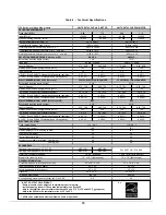
Table 1 - Blower speed adjustments, 4-speed motor
FURNACE
APPLICATION
HEATING OR A/C
OUTPUT
RECOMMENDED
BLOWER SPEED
0.90 USGPH
MED-LOW
HEATING
1.10 USGPH
MED-HIGH
3.0 TONS
LOW
3.5 TONS
MED-LOW
4.0 TONS
MED-HIGH
A/C
5.0 TONS
HIGH
To effect the adjustment, the RED (for heating) and BLUE
(for cooling and heat pump) wires can be changed on the
motor. Also, refer to the position of the wires on the
electronic board of the unit and consult the wiring
diagrams. If the heating and air conditioning speeds are
the same, the RED wire must be moved to “UNUSED
LEADS” on the electronic board and the jumper provided
with the BLUE wire must be used between the “HEAT”
and “COOL” terminals.
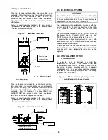
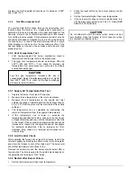
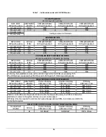
The blower start/stop delays can be adjusted by
positioning the DIP switches on the electronic board as
shown in the following figures. For upflow installation, the
recommended blower ON delay is 60 seconds and blower
OFF delay 2 minutes.
CAUTION
For horizontal and downflow installations only:
Adjust the ON delay to 30 sec.
Adjust the OFF delay to 4 min.
For other adjustments, proceed with tests in order to avoid
cycling.
Figure 8 - Blower Start/Stop Delays
Board # 1158
Summary of Contents for OMF154L20A
Page 18: ...18 Figure 9 Furnace Dimensions...
Page 19: ...19 Figure 10 Wiring diagram 4 speed motor PSC...
Page 20: ...20 Figure 11 Wiring diagram variable speed motor ECM...
Page 21: ...21 Figure 12 Parts list with 4 speed motor PSC B500111A...
Page 23: ...23 Figure 13 Parts list with variable speed motor ECM B50112A...


