Dettson OMF154L20A Installation Instructions And Homeowner'S Manual Download Page 5


5


2 INSTALLATION 

This furnace is a true multi-position unit, in that it will 
function in an upflow, downflow or horizontal configuration 
to the left or the right. Only a few modifications are required 
during installation to change from one position to another. 
The unit is shipped in the upflow configuration and 
instructions as to how to change to the other positions are 
included in this manual. 


The unit is shipped with a burner and its controls. It 
requires a 115VAC power supply to the control panel and 
thermostat hook-up as shown on the wiring diagram, one 
or more oil line connections, suitable ductwork and 
connection to a properly sized vent.  


All local and national code requirements governing the 
installation of oil burning equipment, wiring and the flue 
connection MUST be followed. Some of the codes that 
may apply are: 

CSA B139:


Installation code for oil burning 
equipment. 

ANSI/NFPA 31:

   Installation of oil burning equipment. 

ANSI/NFPA 90B:

 Warm air heating and air conditioning 

systems. 

ANSI/NFPA 211:

  Chimneys, Fireplaces, Vents and solid 

fuel burning appliances.


ANSI/NFPA 70:

   National Electrical Code.  

CSA C22.1 : 

Canadian Electrical Code.


or CSA C22.10


Only the latest issues of these codes may be used. 

2.1 POSITIONING


THE


FURNACE 

WARNING 


Fire and explosion hazard. 


The furnace must be installed in a level position, never 
where it will slope toward the front. 


Do not store or use gasoline or any other flammable 
substances near the furnace. 


Non-observance of these instructions will potentially 
result in death, bodily injury and/or property damage. 


CAUTION 

This furnace is not watertight and is not designed for 
outdoor installation. It must be installed in such a manner 
as to protect its electrical components from water. Outdoor 
installation will lead to a hazardous electrical condition and 
to premature failure of the equipment. 


The minimum clearances from combustible material 
for each of the positions are specified in Table 4. 


If the furnace is installed in a basement or on a dirt floor, in 
a crawl space for example, it is recommended to install the 
unit on a cement base 2.5 cm to 5.0 cm (1" to 2") thick. 

The unit must be installed in an area where the ambient 
and return air temperatures are above 15°C (60°F). In 
addition, the furnace should be installed as closely as 
possible to the vent, so that the connections are direct 
and kept to a minimum. The heater should also be 
located close to the centre of the air distribution system. 
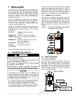
2.1.1 

Installation in an enclosure 

The unit can be installed in an enclosure such as a 
closet. However, 2 ventilation openings are required for 
combustion air. The openings should be located in front 
of the furnace approximately 15 cm (6") above the floor 
and 15 cm (6") below the ceiling. Figure 1 indicates the 
minimum dimensions required and the location of the 
openings.  

Figure 1   -  Location and dimensions of ventilation 

air openings in a closet door 
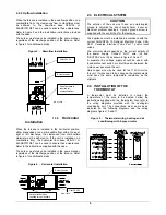
 

2.2 CONFIGURATIONS 


2.2.1 Upflow Installation 

The return air opening may be located on either side of 
the furnace. Care should be taken not to damage the 
wires inside, while cutting the opening. Install the filter 
rack supplied with the unit according to the instructions 
provided with it. It is also recommended to install the 
blower door before handling or moving the unit. Refer to 
figure 2 for additional details.


Figure 2  -  Upflow Installation 


DNS-1227A 

Burner position 

Filter 24X24 

Combustible or non-
combustible floor 

Summary of Contents for OMF154L20A

Page 1: ...FOR THE INSTALLATION SERVICING OF THE FURNACE AND KEEP THE DOCUMENT NEAR THE UNIT FOR FUTURE REFERENCE HOMEOWNER PLEASE KEEP THIS MANUAL NEAR THE FURNACE FOR FUTURE REFERENCE Attention Do not tamper w...

Page 2: ...NEY VENTING 8 2 8 COMBUSTION AIR SUPPLY AND VENTILATION 8 2 9 OIL TANK 9 2 10 DUCTING 9 2 11 SUPPLY AIR ADJUSTMENTS 4 SPEED MOTORS 9 2 12 SUPPLY AIR ADJUSTMENTS ECM VARIABLE SPEED MOTORS 10 2 13 INSTA...

Page 3: ...urnace Dimensions 18 Figure 10 Wiring diagram 4 speed motor PSC 19 Figure 11 Wiring diagram variable speed motor ECM 20 Figure 12 Parts list with 4 speed motor PSC 21 Figure 13 Parts list with variabl...

Page 4: ...formation such as the model and serial numbers of the furnace WARNING Installations and repairs performed by unqualified persons can result in hazards to them and to others Installations must conform...

Page 5: ...designed for outdoor installation It must be installed in such a manner as to protect its electrical components from water Outdoor installation will lead to a hazardous electrical condition and to pre...

Page 6: ...ground to minimize the risk of bodily harm if ever an electrical problem develops A green ground screw is supplied with the control box for that purpose The appliance must be installed in accordance...

Page 7: ...lect nozzle sizes by working back from the desired flow rate at operating pressure and not the nozzle marking 2 5 2 Air and Turbulator Settings Before starting the burner for the first time adjust the...

Page 8: ...of the cool down cycle If the test is not in line with the above call a QUALIFIED SERVICE TECHNICIAN 2 8 COMBUSTION AIR SUPPLY AND VENTILATION WARNING Poisonous carbon monoxide gas hazard Comply with...

Page 9: ...indoor pools c Furnaces installed near chemical storage areas The installation must carefully be verified to ensure that the combustion air comes from outside 2 10 1 Air filter A properly sized air f...

Page 10: ...ier on the HUM terminal It supplies 120 VAC electric power when the burner is in operation A 24 VAC signal can also be supplied from the W and C terminals on the blower electronic board to activate a...

Page 11: ...ing drawn into the suction side of the oil piping and pump Slowly close and tighten the bleed screw Once closed the flame will light up 3 3 2 Pressure adjustment The oil pressure must be adjusted acco...

Page 12: ...duct just outside the range of radiant heat from the heat exchanger 0 3 m 12 from the plenum of the main take off is usually sufficient 4 The temperature rise is calculated by subtracting the return...

Page 13: ...exchanger and combustion chamber should be inspected to determine if replacement is required 8 After the cleaning replace the heat exchanger baffles flue collar plate and oil burner 9 Readjust the bu...

Page 14: ...vice telephone Day Night Dealer name and address START UP RESULTS Nozzle Pressure lb po 2 Burner adjustments Primary air Fine air Drawer Assembly CO2 Smoke scale Bacharach Gross stack temperature F Am...

Page 15: ...Canadian regulation 86 7 85 3 86 7 85 3 AFUE From ASHRAE 103 standard and US regulation 86 3 85 0 86 3 85 0 Volts Hertz Phase Rated current Amps Minimum ampacity for w ire sizing Amps Max fuse size Am...

Page 16: ...ShortRun On Delay CFM Level Time Off Delay CFMLevel Time A 1 OFF 2 OFF 0 90 13 90 sec 31 30 sec 50 4 min B 1 ON 2 OFF 1 10 13 60 sec 31 30 sec 38 5 min C 1 OFF 2 ON ALL 13 90 sec 31 30 sec 56 5 min D...

Page 17: ...OF FURNACE 1 5 08 cm 2 2 54 cm 1 5 08 cm 2 BOTTOM FURNACE 2 2 54 cm 1 3 5 08 cm 2 4 BACK FURNACE OPPOSITE SIDE OF THE BURNER 1 7 62 cm 3 7 62 cm 3 7 62 cm 3 PLENUM OR HORIZONTAL WARM AIR DUCT WITHIN...

Page 18: ...18 Figure 9 Furnace Dimensions...

Page 19: ...19 Figure 10 Wiring diagram 4 speed motor PSC...

Page 20: ...20 Figure 11 Wiring diagram variable speed motor ECM...

Page 21: ...21 Figure 12 Parts list with 4 speed motor PSC B500111A...

Page 22: ...WIRE CHANNEL INT 30 B03829 BLOWER DIVIDER 31 B03838 BLOWER SLIDE One blower slide included 32 B03835 02 LATERAL BAFFLE 33 B03867 01 FILTER RACK KIT 34 B03828 FLOOR 35 B03855 02 SIDE PANEL ASSEMBLY LE...

Page 23: ...23 Figure 13 Parts list with variable speed motor ECM B50112A...

Page 24: ...NNEL INT 29 B03829 BLOWER DIVIDER 30 B03838 BLOWER SLIDE One blower slide included 31 B03835 02 LATERAL BAFFLE 32 B03867 01 FILTER RACK KIT 33 B03828 FLOOR 34 B03855 02 SIDE PANEL ASSEMBLY LEFT Panel...

Reviews: