Dettson OMF154L20A Installation Instructions And Homeowner'S Manual Download Page 17


 17


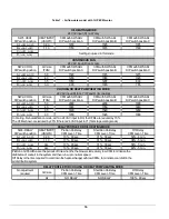
Table 8  -  Airflow data model with 1HP 4-speed motor 


Table 9  -  Minimum clearances from combustible materials 


0.2" (W.C.)

0.3" (W.C.)

0.4" (W.C.)

0.5" (W.C.)

0.6" (W.C.)

0.7" (W.C.)

HIGH

2130

2085

1995

1915

1820

1745

MED-HIGH

1930

1855

1800

1750

1675

1615

MED-LOW

1565

1495

1460

1430

1400

1360

LOW

1185

1170

1140

1105

1080

1065

BLOWER

SPEED

EXTERNAL STATIC PRESSURE WITH AIR FILTER

UPFLOW

HORIZONTAL

DOWNFLOW

FURNACE 

1

2.54 cm (1")

N/A

5.08 cm (2")

PLENUM AND WARM-AIR DUCT WITHIN 6 ft. OF FURNACE 

1

5.08 cm (2")

2.54 cm (1")

5.08 cm (2")

BOTTOM

FURNACE 

2

Ø

2.54 cm (1")

3

5.08 cm (2")

4

BACK

FURNACE (OPPOSITE SIDE OF THE BURNER) 

1

7.62 cm (3")

7.62 cm (3")

7.62 cm (3")

PLENUM OR HORIZONTAL WARM-AIR DUCT WITHIN 6 ft. OF FURNACE 

2

5.08 cm (2")

7.62 cm (3")

5.08 cm (2")

FURNACE 

2

N/A

5.08 cm (2")

N/A

FLUE PIPE

AROUND FLUE PIPE

22.86 cm (9")

22.86 cm (9")

22.86 cm (9")

FRONT

FURNACE (BURNER SIDE) 

1

45.72 cm (18")

45.72 cm (18")

45.72 cm (18")

These are horizontal dimensions 

These are vertical dimensions

3


This dimension can be obtained by using Horizontal Flow Base # HFB-101 or # KLASB0701DET

4


This dimension can be obtained by using Downflow Base # DFB-104 or # KLASB1001DET

LOCATION

SIDES

TOP

Summary of Contents for OMF154L20A

Page 1: ...FOR THE INSTALLATION SERVICING OF THE FURNACE AND KEEP THE DOCUMENT NEAR THE UNIT FOR FUTURE REFERENCE HOMEOWNER PLEASE KEEP THIS MANUAL NEAR THE FURNACE FOR FUTURE REFERENCE Attention Do not tamper w...

Page 2: ...NEY VENTING 8 2 8 COMBUSTION AIR SUPPLY AND VENTILATION 8 2 9 OIL TANK 9 2 10 DUCTING 9 2 11 SUPPLY AIR ADJUSTMENTS 4 SPEED MOTORS 9 2 12 SUPPLY AIR ADJUSTMENTS ECM VARIABLE SPEED MOTORS 10 2 13 INSTA...

Page 3: ...urnace Dimensions 18 Figure 10 Wiring diagram 4 speed motor PSC 19 Figure 11 Wiring diagram variable speed motor ECM 20 Figure 12 Parts list with 4 speed motor PSC 21 Figure 13 Parts list with variabl...

Page 4: ...formation such as the model and serial numbers of the furnace WARNING Installations and repairs performed by unqualified persons can result in hazards to them and to others Installations must conform...

Page 5: ...designed for outdoor installation It must be installed in such a manner as to protect its electrical components from water Outdoor installation will lead to a hazardous electrical condition and to pre...

Page 6: ...ground to minimize the risk of bodily harm if ever an electrical problem develops A green ground screw is supplied with the control box for that purpose The appliance must be installed in accordance...

Page 7: ...lect nozzle sizes by working back from the desired flow rate at operating pressure and not the nozzle marking 2 5 2 Air and Turbulator Settings Before starting the burner for the first time adjust the...

Page 8: ...of the cool down cycle If the test is not in line with the above call a QUALIFIED SERVICE TECHNICIAN 2 8 COMBUSTION AIR SUPPLY AND VENTILATION WARNING Poisonous carbon monoxide gas hazard Comply with...

Page 9: ...indoor pools c Furnaces installed near chemical storage areas The installation must carefully be verified to ensure that the combustion air comes from outside 2 10 1 Air filter A properly sized air f...

Page 10: ...ier on the HUM terminal It supplies 120 VAC electric power when the burner is in operation A 24 VAC signal can also be supplied from the W and C terminals on the blower electronic board to activate a...

Page 11: ...ing drawn into the suction side of the oil piping and pump Slowly close and tighten the bleed screw Once closed the flame will light up 3 3 2 Pressure adjustment The oil pressure must be adjusted acco...

Page 12: ...duct just outside the range of radiant heat from the heat exchanger 0 3 m 12 from the plenum of the main take off is usually sufficient 4 The temperature rise is calculated by subtracting the return...

Page 13: ...exchanger and combustion chamber should be inspected to determine if replacement is required 8 After the cleaning replace the heat exchanger baffles flue collar plate and oil burner 9 Readjust the bu...

Page 14: ...vice telephone Day Night Dealer name and address START UP RESULTS Nozzle Pressure lb po 2 Burner adjustments Primary air Fine air Drawer Assembly CO2 Smoke scale Bacharach Gross stack temperature F Am...

Page 15: ...Canadian regulation 86 7 85 3 86 7 85 3 AFUE From ASHRAE 103 standard and US regulation 86 3 85 0 86 3 85 0 Volts Hertz Phase Rated current Amps Minimum ampacity for w ire sizing Amps Max fuse size Am...

Page 16: ...ShortRun On Delay CFM Level Time Off Delay CFMLevel Time A 1 OFF 2 OFF 0 90 13 90 sec 31 30 sec 50 4 min B 1 ON 2 OFF 1 10 13 60 sec 31 30 sec 38 5 min C 1 OFF 2 ON ALL 13 90 sec 31 30 sec 56 5 min D...

Page 17: ...OF FURNACE 1 5 08 cm 2 2 54 cm 1 5 08 cm 2 BOTTOM FURNACE 2 2 54 cm 1 3 5 08 cm 2 4 BACK FURNACE OPPOSITE SIDE OF THE BURNER 1 7 62 cm 3 7 62 cm 3 7 62 cm 3 PLENUM OR HORIZONTAL WARM AIR DUCT WITHIN...

Page 18: ...18 Figure 9 Furnace Dimensions...

Page 19: ...19 Figure 10 Wiring diagram 4 speed motor PSC...

Page 20: ...20 Figure 11 Wiring diagram variable speed motor ECM...

Page 21: ...21 Figure 12 Parts list with 4 speed motor PSC B500111A...

Page 22: ...WIRE CHANNEL INT 30 B03829 BLOWER DIVIDER 31 B03838 BLOWER SLIDE One blower slide included 32 B03835 02 LATERAL BAFFLE 33 B03867 01 FILTER RACK KIT 34 B03828 FLOOR 35 B03855 02 SIDE PANEL ASSEMBLY LE...

Page 23: ...23 Figure 13 Parts list with variable speed motor ECM B50112A...

Page 24: ...NNEL INT 29 B03829 BLOWER DIVIDER 30 B03838 BLOWER SLIDE One blower slide included 31 B03835 02 LATERAL BAFFLE 32 B03867 01 FILTER RACK KIT 33 B03828 FLOOR 34 B03855 02 SIDE PANEL ASSEMBLY LEFT Panel...

Reviews: