


4
2 INSTALLATION
The unit is shipped with a burner and its controls. It requires a
115VAC power supply to the control panel and thermostat
hook-up as shown on the wiring diagram, one or more oil line
connections, suitable ductwork and connection to a properly
sized vent.
All local and national code requirements governing the
installation of oil burning equipment, wiring and the flue
connection MUST be followed. Some of the codes that may
apply are:
CSA B139:
Installation code for oil burning equipment.
ANSI/NFPA 31:
Installation of oil burning equipment.
ANSI/NFPA 90B:
Warm air heating and air conditioning
systems.
ANSI/NFPA 211:
Chimneys, Fireplaces, Vents and solid fuel
burning appliances.
ANSI/NFPA 70:
National Electrical Code.
CSA C22.1 or
CSA C22.10
:
Canadian Electrical Code.
Only the latest issues of these codes may be used.
2.1
POSITIONING THE FURNACE
WARNING
Fire and explosion hazard.
The furnace must be installed in a level position, never
where it will slope toward the front.
Do not store or use gasoline or any other flammable
substances near the furnace.
Non-observance of these instructions will potentially result
in death, bodily injury and/or property damage.
CAUTION
This furnace is not watertight and is not designed for outdoor
installation. It must be installed in such a manner as to protect
its electrical components from water. Outdoor installation will
lead to a hazardous electrical condition and to premature
failure of the equipment.
The minimum clearances from combustible material for
each of the positions are specified in Table 4.
If the furnace is installed in a basement or on a dirt floor, in a
crawl space for example, it is recommended to install the unit
on a cement base 2.5 cm to 5.0 cm (1" to 2") thick.
The unit must be installed in an area where the ambient and
return air temperatures are above 15°C (60°F). In addition, the
furnace should be installed as closely as possible to the vent,
so that the connections are direct and kept to a minimum. The
heater should also be located close to the centre of the air
distribution system.
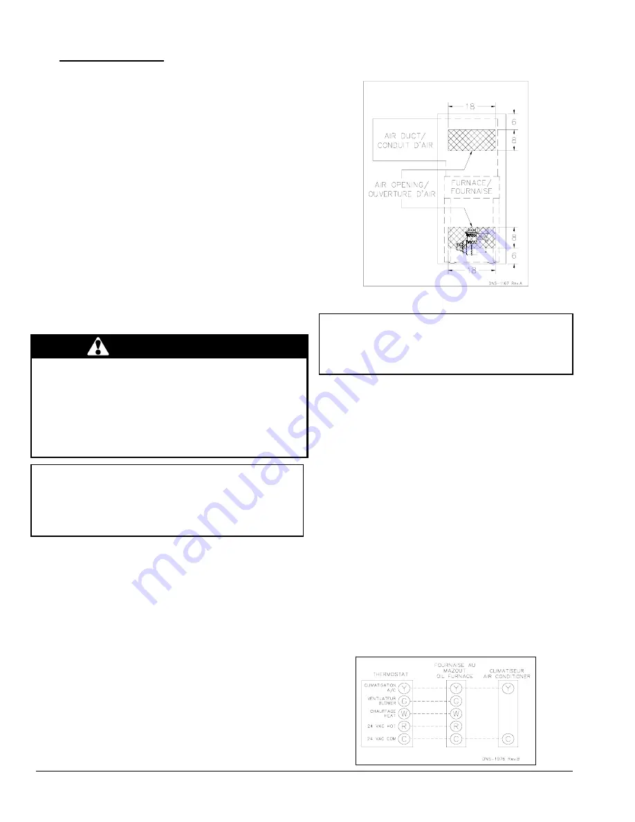
2.1.1 Installation in an enclosure
The unit can be installed in an enclosure such as a closet.
However, 2 ventilation openings are required for combustion
air. The openings should be located in front of the furnace
approximately 15 cm (6") above the floor and 15 cm (6") below
the ceiling. Figure 1 indicates the minimum dimensions
required and the location of the openings.
Figure 1: Location and dimensions of ventilation air
openings in a closet door
2.2 ELECTRICAL
SYSTEM
CAUTION
The exterior of the unit must have an uninterrupted ground
to minimize the risk of bodily harm, if ever an electrical
problem develops. A green ground screw is supplied with
the control box for that purpose.
The appliance must be installed in accordance with the
current ANSI/NFPA 70 National Electrical Code, CSA
C22.1 Canadian Electrical Code Part 1 and/or local codes.
The control system depends on the correct polarity of the
power supply. Connect “HOT” wire (H) and “NEUTRAL”
wire (N) as shown in Figures 3 and 4.
A separate line voltage supply should be used, with fused
disconnect switch or circuit breaker, between the main
power panel and the unit.
Only copper wire may be used for the 115V circuit on this
unit. If wires need to be changed, the replacements must
have the same temperature resistance as the originals.
2.3
INSTALLATION OF THE THERMOSTAT
A thermostat must be installed to control the temperature
of the area to be heated. Follow the instructions supplied
with the thermostat. Also refer to the wiring diagrams
provided with the heating/air conditioning unit. The
connections must be made as indicated on the following
diagrams and the wiring diagrams.
Figure 2: Heating & Air Conditioning - With 4 Speed
Motor
Summary of Contents for AMT154SDMA
Page 16: ...16 Figure 7 Furnace Dimensions...
Page 17: ...17 Figure 8 Wiring Diagram 4 Speed Motor PSC...
Page 18: ...18 Figure 9 Wiring Diagram Variable Speed Motor ECM...
Page 19: ...19 Figure 10 Parts List With 4 Speed motor PSC B50095B...
Page 21: ...21 Figure 11 Parts List With variable speed motor ECM B50096C...


