


14
EDX
Series
3.0
Installation
•
Hanger Placement and Suspension
Suspension of the heater must conform to applicable codes referenced in the Safety section and these
instructions.
3
Prepare the mounting surface, if necessary, such as weld blocks or drill holes. See Figure 3.5.
NOTE:
The burner control box and radiant tubes should be in straight alignment and level.
4
Fasten beam clamp, screw hook, or other type of suspension anchor to hanging point.
5
Attach and close S-hook and #1 double-loop chain to anchor. Check that it is securely attached.
NOTE:
Threaded rod and turnbuckles may be used.
6
Attach hangers to chains. Adjust chain lengths until radiant tubing is level and equal weight distribution
is achieved.
NOTE:
Chains must be straight up and down. Do not install chains at an angle as this can
result in tube warpage or separation. Gripple
®
may also be used.
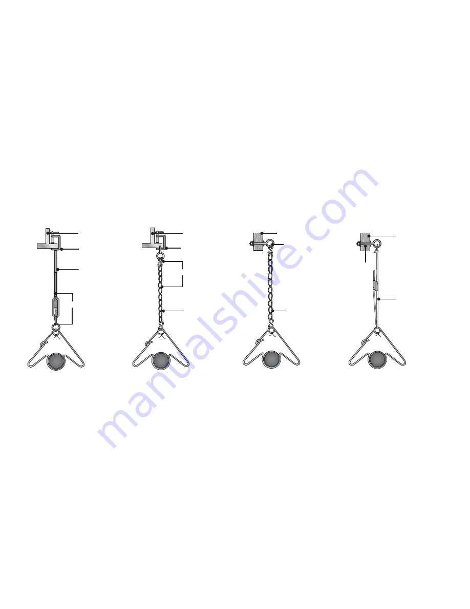
Figure 3.5
•
Mounting the Hangers
5
S-Hook and
#1 double-loop
chain
3
Wood
Beam
3
Concrete Beam
4
Beam Clamp
4
Screw Hook
4
Screw hook
with
locknut
and
washer
5
Threaded Rod
and Turnbuckle
6
Threaded Rod
6
Chain
3
I-Beam
4
Beam Clamp
6
Chain
6
Gripple
3
I-Beam