


Model 610-N4X-SA
TB1
AC INPUT
ALARM OUTPUTS
DRY CONTACTS
ALARM RELAYS K1 - K5
H2S LOW
H2S HIGH
FAULT
LEL LOW
LEL HIGH
21
22
23
30
32
33
34
35
24
25
26
27
28
29
36
37
38
45
46
47
48
49
50
39
40
41
42
43
44
7
8
9
10
16
17
18
19
20
5
6
1
2
3
11
12
13
14
15
4
ALM 2
ALM 1
FAULT
MODEL 10
ALARM
RESET
TEST
ALM 2
ALM 1
FAULT
MODEL 10
ALARM
RESET
TEST
ALM 2
ALM 1
FAULT
MODEL 10
ALARM
RESET
TEST
ALM 2
ALM 1
FAULT
MODEL 10
ALARM
RESET
TEST
ALM 2
ALM 1
FAULT
MODEL 10
ALARM
RESET
TEST
ALM 2
ALM 1
FAULT
MODEL 10
ALARM
RESET
TEST
K1
K2
K3
8
6
5
4
3
1
2
7
8
6
5
4
3
1
2
7
8
6
5
4
3
1
2
7
8
6
5
4
3
1
2
7
K5
K4
8
6
5
4
3
1
2
7
CH1-6 : 4-20mA
SENSOR INPUTS
610 - Mother Board
A1
AL
M
1
GND
ALM COIL
COMMON ALARMS
ALM 1
FAULT
VDC-
ALM 2
-
+
RS-485
ALM POWER
L1
N
+
-
N
GND
A(+)
B(-)
Shld
OU
T
4-
20
F
A
U
L
T
-
NO
+
C
NC
NO
C
VDC IN
ALM RESET
L1
-
+
SEN
SOR
ALM
2
NC
NO
C
NC
mA
-
CH1
+
CH2
CH3
CH5
CH4
CH6
VAC IN
P4
P5
P7
P7
P8
P9
P10
N
GND
L1
PS VAC
P3
PS DC
-
+
P2
BRKR
-
+
P1
Lo
w Vol
ta
ge
Cut
-O
ff
TB2
TB3
Battery
Backup
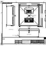
Figure 3
Component Layout
AC INPUT
ALARM OUTPUTS
H2S LOW
H2S HIGH
FAULT
DRY CONTACTS
1
2 3
4
5 6 7 8 9 10 11 12 13 14
15
16
17
18
19
20
21
22
23
TB1 - 3 Relay Unit
Neutral
Rtn
H2S LOW
H2S
H
IGH
FAULT
42
43
44
50
46
45
48
47
49
22
H2S LOW
ALARM OUTPUTS
TB1 - 5 Relay Unit
Neutral
Rtn
8
AC INPUT
3
2
1
4
6
5
7
19
13
12
11
10
9
15
14
18
17
16
20
21
40
H2
S HI
G
H
DRY CONTACTS
LEL LOW
H2S HIGH
FAULT
24
23
26
25
28
27
29
30
LEL HIGH
H2
S L
O
W
33
32
35
34
39
38
37
36
FA
UL
T
LEL L
O
W
LEL H
IGH
50
45
43
44
41
42
49
47
48
46
Figure 4
Alarm Wiring
610-N4X-SA Instruction Manual
Rev. 0.1
Page 5 of 8