


Model 610-N4X-SA
1.0 Introduction
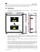
Detcon Model 610-N4X-SA Gas Detection System consists of 3 major assemblies:
1. The 610-N4X-SA Fiberglass or Stainless Steel control enclosure.
2. The Model 10 single channel digital control modules.
3. The remote mount gas sensor assemblies.
The NEMA 4X control enclosure is detailed in this manual, the Model 10 digital control modules are detailed
in the Detcon Model 10 Operators Installation and Instruction Manual, and applicable sensor assemblies in
their corresponding Operators Installation and Instruction Manual.
1.1 Description
Detcon Model 610-N4X-SA control enclosure, along with Model 10 digital control modules, is designed to
serve as a host assembly for up to six remote mount gas detection sensor assemblies. The control enclosure is
rated NEMA 4X, which is by definition rain tight and therefore suitable for outdoor location in electrically
non-hazardous environments. The single channel modular design supports application flexibility wherein one
or two gas detection systems are configured dependent on the three or five alarm relay model. All control
modules are plug-in front panel accessible for easy maintenance and repair. The system is powered by
120VAC unless otherwise specified at the time of order.
Discrete output terminal strips located on the controller motherboard are provided for sensor terminations. The
4-20 mA outputs for remote recording devices and an RS-485 serial ModBus™ output are located on the
motherboard. The VDC power in, and remote alarm reset terminations are also provided on the Motherboard.
Din Rail mounted terminal block outputs are provided for two or four alarm and one fault relays.
Terminations for AC power-in are also provided on a Din Rail.
All Relays on the Model 10 digital control modules are configured as Latched, Normally Energized in No-
Alarm/No-Fault condition. These relays control the state of the Alarm Relays mounted on the motherboard.
Each Alarm Relay is a DPDT relay with one set of contacts for annunciator power and one set of dry contacts
for customer use. Three – 5Amp Fuse Blocks are provided for each alarm, providing the ability to connect up
to three annunciators for each alarm condition (including Fault).
1.2 Specifications
Electrical Classification
NEMA
4X
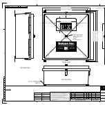
Dimensions
24''W x 24''H x 10 1/2''D
Capacity
6 single channels
Power Input
220VAC/117VAC/24VDC
Power Consumption
<5 watts per channel (includes gas sensor and control modules. Does not include annunciators.)
Outputs
Discrete Analog 4-20 mA DC
Serial RS-485 Modbus™
Discrete or zoned alarm relays (Alarm 2 Timer(s))
Discrete alarm relays K1, K3 (and if applicable K4)
Resistive load: 7.5A, 240 VAC; 10A, 30 VDC
610-N4X-SA Instruction Manual
Rev. 0.1
Page 1 of 8