Detcon 610-N4X-SA Operator'S Installation And Instruction Manual Download Page 10

Model 610-N4X-SA

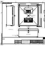
6. Each alarm has an associated set of dry contacts from the Alarm/Fault relay’s (Figure 3 and Figure 5). 

These dry contact terminals consist of a Common relay connection through a terminal disconnect, and 
the NC and NO Contacts via through terminals (Figure 4). 

24 25 26

CO

M

NC

NO

Disconnect Terminal Block

Through Terminal Block

COM - Common

NC - Normally Closed
NO - Normally Open

Figure 5 

Typical Dry Contact Connections

7. If applicable, connect a 24VDC source or standby battery to the terminal strip labeled “VDC IN” (+ 

and –) on the Motherboard (Figure 2). 

8. Connect 117VAC input to the Circuit Breaker labeled “VAC IN” in the lower left of the enclosure

(Figure 3 and L1, N, EARTH in Figure 6).  If applicable, connect 220VAC.  The power supply will 
accept both voltages.

9. Connect Earth Ground to Terminal TB1-1, and Neutral to terminal TB1-5 (Figure 6). 

7

8

9

5

6

1

2

3

G

rou

nd

 / 

Ear

th

 V

A

C

 In

pu

t / 

L1

Ne

ut

ra

l /

 N

20Amp

Brkr

4

ON

Figure 6 

Input Power Connections

2.1 Start 

Up

Upon completion of all field wiring: Apply power to the 610-N4X-SA by turning the 20Amp Circuit Breaker 
ON.  Note that each Model 10 controller digital display illuminates.  Note; varying readings may occur during
sensor warm-up.  A 10 second alarm delay will occur on power up.  Refer to the applicable Sensor Instruction
Manual for additional sensor start-up details.

3.0 Maintenance & Repair 

The Detcon Model 610-N4X-SA’s modular design allows for minimum ‘down-time’ during maintenance
and/or repair.

610-N4X-SA Instruction Manual

Rev. 0.1

Page 6 of 8 

Summary of Contents for 610-N4X-SA

Page 1: ...ouston Texas Gas Detection Control System www detcon com Houston Texas Detcon Inc Operator s Installation and Instruction Manual Covers 3 and 5 relay Stainless and Fiberglass Enclosures DETCON Inc 320...

Page 2: ...Model 610 N4X SA This page left intentionally blank 610 N4X SA Instruction Manual ii...

Page 3: ...2 1 Start Up 6 3 0 Maintenance Repair 6 4 0 Spare Parts List 8 5 0 Warranty 8 Table of Figures Figure 1 Mounting 3 Figure 2 Motherboard Schematic Wiring Diagram 4 Figure 3 Component Layout 5 Figure 4...

Page 4: ...ank Shipping Address 3200 A 1 Research Forest Dr The Woodlands Texas 77381 Mailing Address P O Box 8067 The Woodlands Texas 77387 8067 Phone 888 367 4286 281 367 4100 Fax 281 292 2860 www detcon com s...

Page 5: ...r Discrete output terminal strips located on the controller motherboard are provided for sensor terminations The 4 20 mA outputs for remote recording devices and an RS 485 serial ModBus output are loc...

Page 6: ...le applying power to annunciators attached to alarm 1 H2S or LEL Low Alarm 1 conditions can be Acknowledged and Reset via the RESET ACK Switch on the front panel of the unit Alarm 2 H2S LEL High Durin...

Page 7: ...MODEL 10 MODEL 10 MODEL 10 MODEL 10 MODEL 10 MODEL 10 Model 610 N4X www detcon com d e t c o n I n c Figure 1 Mounting 2 Refer to installation and wiring detail of remote mount sensor assemblies as d...

Page 8: ...6 5 4 3 2 1 14 13 12 11 10 9 8 7 6 5 4 3 2 1 CH1 P12 P16 CH1 4 20mA FAULT VDC Alarm 2 Alarm 1 Fault Out COM NC ALM1 ALM2 GND Shld B A VDC VAC GND VDC N L1 RED BLK N L1 Sensor NO COM NO NC COM NO NC m...

Page 9: ...D ALM COIL COMMON ALARMS ALM 1 FAULT VDC ALM 2 RS 485 ALM POWER L1 N N GND A B Shld OUT 4 20 FAULT NO C NC NO C VDC IN ALM RESET L1 SENSOR ALM2 NC NO C NC mA CH1 CH2 CH3 CH5 CH4 CH6 VAC IN P4 P5 P7 P7...

Page 10: ...sure Figure 3 and L1 N EARTH in Figure 6 If applicable connect 220VAC The power supply will accept both voltages 9 Connect Earth Ground to Terminal TB1 1 and Neutral to terminal TB1 5 Figure 6 7 8 9 5...

Page 11: ...gure 7 Backplane Configuration Jumpers Model 10 Control Modules A Model 10 control module may be changed by simply loosening its mounting screw and sliding the module out of its card cage See the Mode...

Page 12: ...ircuit Breaker 500 505000 000 Low Voltage Cut off PCB If applicable 3423 2 12V 2 9Ah Battery If applicable 5 0 Warranty Detcon Inc as manufacturer warrants under intended normal use each new Model 610...

Page 13: ......

Page 14: ......

Page 15: ......

Page 16: ......

Page 17: ......

Page 18: ......

Page 19: ......

Page 20: ......

Reviews: