Det-Tronics U7652 Instructions Manual Download Page 7

INSTALLATION

DETECTOR POSITIONING

Detectors should be positioned to provide the best
unobstructed view of the area to be protected.  The
following factors should also be taken into considera-
tion:

• Locate and position the detector so that the fire haz-

ard(s) are within both the field of view and detection
range of the device.  Refer to Appendix A for specific
information.

• Considering the 90 degree cone of vision, use

enough detectors to adequately cover the protected
area with overlapping cones of vision.

• For fastest response time, position the detectors as

close as possible to the anticipated fire source.

• Aim the detector with the anticipated fire source as

close as possible to the central axis of the cone of
vision.

• If possible, conduct actual flame tests to verify cor-

rect detector positioning and proper system opera-
tion.

• Position the detector in a manner that will minimize

the buildup of contaminants on the viewing window
and 

oi

ring.  Substances such as snow, ice, dirt, oil,

paint overspray and numerous other commonly
encountered materials are capable of attenuating
UV or IR radiation and adversely affecting detector
response.

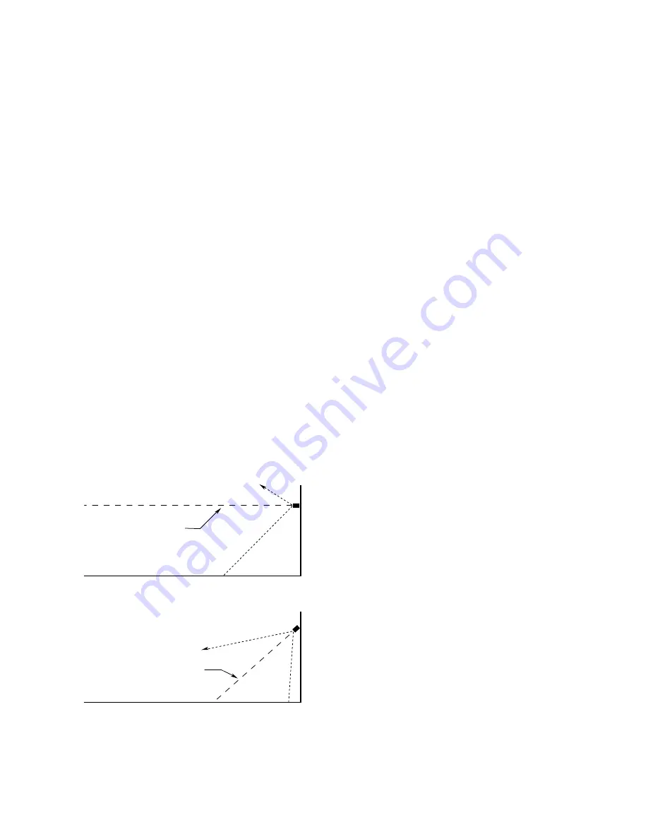
• For outdoor applications, the detector should be

aimed downward at least 10 to 20 degrees to prevent
it from scanning the horizon.  This minimizes response
to distant UV sources outside the protected area.  See
Figure 1.

• The detector should not be placed where smoke

can obscure its view of the hazardous area.  For
indoor applications, if dense smoke is expected to
accumulate at the onset of a fire, mounting the
detector on a side wall a few feet (1 meter) down
from the ceiling will normally allow enough time for
the unit to respond before it is affected by rising
smoke.

WIRING REQUIREMENTS

• Use 16 to 22 gauge (1.5 to 0.5 mm

2

) cable.  

• A minimum input voltage of 18 vdc must be present

at the detector.  

• Use cable that is suitable for the installation environ-

ment (harsh environments require specially made
cable).

• Shielded cable is highly recommended to protect

against interference caused by extraneous electri-
cal “noise.”  Foil type shielded cable is recommend-
ed to protect from electromagnetic and radio fre-
quency interference.  When using cables with
shields, the shield should be insulated at the detec-
tor and grounded only at the control cabinet.

• When cable is installed in conduit, the conduit

should not be used for wiring to other electrical
equipment.  

• When cable is installed in conduit, the use of con-

duit seals is required to prevent damage to electri-
cal connections caused by condensation within the
conduit. These seals must be watertight and explo-
sion-proof and are to be installed even if they are
not required by local wiring codes.  A seal must be
located as close to the U7652 as possible.  In no
case should this seal be located more than 18 inch-
es (46 cm) from the unit.  If a conduit swivel is used,
the seal must be located between the swivel and
the detector.  When an explosion-proof installation is
required, an additional seal must also be installed at
any point where the conduit enters a non-hazardous
area.  

• When cable glands are used, water-proof seals

must be fitted between the housing and the gland.

• Position the detector so that the conduit opening is

at the bottom or at either side of the device. 

• Whenever possible, slope the conduit run down-

ward from the detector.  Do not use conduit runs
that enter the device from the top.  Refer to Figures
2 and 3.

5

95-8385

CENTER AXIS 
OF DETECTOR 
FIELD OF VIEW

CENTER AXIS 
OF DETECTOR 
FIELD OF VIEW

INCORRECT

CORRECT

NOTE: DETECTOR MUST ALWAYS BE AIMED

DOWNWARD AT LEAST 10 TO 20 DEGREES.

B1974

Figure 1—Detector Orientation Relative to Horizon

Summary of Contents for U7652

Page 1: ...tions 95 8385 06 Unitized UV IR Flame Detector U7652 Detector Electronics Corporation 6901 West 110th Street Minneapolis Minnesota 55438 USA Tel 952 941 5665 or 800 765 3473 Fax 952 829 8750 3 01 95 8...

Page 2: ...7 Figure 7 U7652B Wiring Terminal Configuration 7 Figure 8 Wiring Terminal Configuration for U7652C with Auxiliary Relay 7 Figure 9 Wiring Terminal Configuration for U7652C with 4 to 20 ma Output 8 F...

Page 3: ...ouch the connector circuit board or electronic components 4 Alarm and extinguishing devices should be disconnected before performing the manual oi test DESCRIPTION The U7652 UV IR Flame Detector is an...

Page 4: ...ormally de energized no fire Energizes upon detection of fire Field programmable for either latching or non latching operation Fault relay has SPST normally open contacts Normally energized no fault D...

Page 5: ...is 10 degrees and were set for a 0 5 second time delay Response is dependent on the type of fuel the temperature of the fuel and the time required for the fire to build As with all fire tests results...

Page 6: ...erence by EMI and RFI It will not respond to a 5 watt walkie talkie at a dis tance of greater than 1 foot VIEWING WINDOWS Keep the detector viewing windows as free of con taminants as possible in orde...

Page 7: ...IREMENTS Use 16 to 22 gauge 1 5 to 0 5 mm2 cable A minimum input voltage of 18 vdc must be present at the detector Use cable that is suitable for the installation environ ment harsh environments requi...

Page 8: ...SWIVEL CONDUIT SEAL A1478 Figure 3 Vertical Mounting B1437 TERMINAL BLOCK AUXILIARY RELAY OPERATION W4 LATCH NON LATCH W1 ALARM RESPONSE W3 oi TEST W2 CONNECTOR SCREWS 3 MOTHERBOARD ASSEMBLY Figure 4...

Page 9: ...LT RELAY IS SHOWN DE ENERGIZED BUT IS NORMALLY ENERGIZED WITH POWER APPLIED AND NO FAULTS PRESENT 9 8 7 6 5 4 3 2 1 9 8 7 6 5 4 3 2 1 FIRE FAULT CON 1 CON 2 AUX AUX Figure 8 Wiring Terminal Configurat...

Page 10: ...CON 1 CON 1 CON 2 CON 2 SPARE FAULT RELAY 0 47 F 400 VOLT CAPACITOR Figure 10 A Typical System Using U7652B Detectors FAULT RELAY IS SHOWN DE ENERGIZED BUT IS NORMALLY ENERGIZED WITH POWER APPLIED AND...

Page 11: ...used pour the conduit seals and allow them to dry 7 Re install the junction box cover ensuring that the 9 pin D connectors are properly mated between the cover and the circuit board inside the enclo s...

Page 12: ...e unit is programmed for non latch ing operation the Fire relay will become de ener gized and the LEDs will turn off when the UV IR source is removed If the unit is programmed for latching operation i...

Page 13: ...und faults power supply transients and lightning strikes All Det Tronics systems are designed with extensive protec tion circuitry however damage can still occur The following field test procedure has...

Page 14: ...background Background radiation as such does not cause a problem Radiation UV or IR radiation is indicated with the detector in most applications unless both UV and by steady illumination of the flick...

Page 15: ...proper operation is observed If abnormal operation is evident start with the sensor exchange first then the detector cover assembly and finally the detector mother board assembly Always remove system...

Page 16: ...e sensor housing Hand tighten the sensor housing into the base until the O ring is fully seated 8 Re install the cover locking device if used 9 Inspect the viewing windows and oi rings and clean if ne...

Page 17: ...to the detector terminal blocks 8 Apply a small amount of lubricant to each of the six screws on the junction box cover Line up the D connector on the junction box cover with the connector on the mot...

Page 18: ...sure that they are properly seated in the groove on the hous ing It is imperative that these O rings be properly installed and in good condition Failure to maintain these rings can allow water to ente...

Page 19: ...cond ENCLOSURE MATERIAL Copper free aluminum red or 316 stainless steel with stainless steel mounting bracket TEMPERATURE RATING Operating 40 F to 167 F 40 C to 75 C Storage 40 F to 185 F 40 C to 85 C...

Page 20: ...See Figures 5 and 6 MTBF 36 183 hours SHIPPING WEIGHT Approximate Pounds Kilograms Aluminum housing 6 0 2 7 Stainless steel housing 14 0 6 3 REPLACEMENT PARTS The electronic module is not designed to...

Page 21: ...R Long Range Test Lamp RECOMMENDED SPARE PARTS oi ring for UV detector 1 per 10 units oi ring for IR detector 1 per 10 units O rings for UV and IR detectors 2 per 10 units UV module with LEDs 1 per 10...

Page 22: ...ollowing performance criteria was verified by FMR using IR Module DE 5400 001 and UV Module DE1888 Response Characteristics Angle of View 45 to 45 off centerline in vertical and horizontal planes Fals...

Page 23: ...Printed in USA Detector Electronics Corporation 6901 West 110th Street Minneapolis Minnesota 55438 USA Tel 952 941 5665 or 800 765 3473 Fax 952 829 8750...

Reviews: