background image

www.fmiproducts.com

124387-01A

11

VENTING INSTALLATION

A FMI PRODUCTS, LLC or an 8" B-type vent-
ing system must be connected to appliance for 
venting to the outside of building. Transition 
pipe model BTC-8 is required for use with 
B-type venting.
Standing codes requirements concerning 
vent installations may vary within your state, 
province or local codes jurisdiction. Therefore, 
it is recommended that you check with your 

ORFDOEXLOGLQJFRGHVIRUVSHFL¿FUHTXLUHPHQWV

or in absence of local codes, follow Section 
7.0 of the current 

National Fuel Gas Code 

ANSI Z223.1/NFPA 54

.

This gas appliance must be vented to the 
outdoors only and may not be terminated into 

DQDWWLFVSDFHRULQWRDFKLPQH\ÀXHVHUYLFLQJ

a solid-fuel burning appliance.

Vent terminations must be located in ac-
cordance with height and proximity rules of 
NFPA No. 54. These rules apply to vents at 
12" diameter or less and require a minimum 
height in accordance with the roof pitch and a 
minimum of 8 ft. distance from a vertical wall 
or obstruction (see Figure 11).

 WARNING: This appliance 

PXVW EH SURSHUO\ FRQQHFWHG
WR D V\VWHP DQG PXVW QRW EH
FRQQHFWHG WR D FKLPQH\ ÀXH

servicing a separate solid fuel 

EXUQLQJDSSOLDQFH

Lowest
Discharge
Opening

Listed
Vent Cap

8 Ft. Min.

Roof Pitch x/12
Listed Clearance

12

x

Listed
Gas
Vent

H (Min)
Height
From Roof

Figure 11 - Typical Terminations

Roof Pitch

H (Min.)

Feet

Meter

Flat to 6/12

1.0

0.30

6/12 to 7/12

1.25

0.38

Over 7/12 to 8/12

1.5

0.46

Over 8/12 to 9/12

2.0

0.61

Over 9/12 to 10/12

2.5

0.76

Over 10/12 to 11/12

3.25

0.99

Over 11/12 to 12/12

4.0

1.22

Over 12/12 to 14/12

5.0

1.52

Over 14/12 to 16/12

6.0

1.83

Over 16/12 to 18/12

7.0

2.13

Over 18/12 to 20/12

7.5

2.27

Over 20/12 to 21/12

8.0

2.44

1

/

2

"

(3.8 cm)

Max.

3" (7.6 cm)

Max.

6" (15.2 cm)

Max.

9"

(22.9 cm)

12"

(30.5 cm)

Outer 
Surround

Combustible
Material May
Be Used

TOP VIEW

SAFE
ZONE

Perpendicular
Wall

33°

Figure 10 - Side Clearances - Top View (Cross Section)

PRE INSTALLATION PREPARATION

Continued

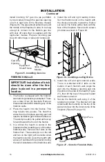
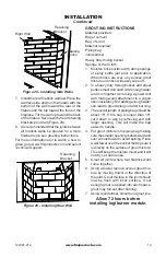
Summary of Contents for BBM-36N-JHB

Page 1: ...EOH vapors or liquids in the vicinity of this or any other appliance WHAT TO DO IF YOU SMELL GAS R QRW WU WR OLJKW DQ DSSOLDQFH R QRW WRXFK DQ HOHFWULFDO VZLWFK R QRW XVH DQ SKRQH LQ RXU EXLOGLQJ PPHGLDWHO FDOO RXU JDV VXSSOLHU IURP D QHLJKERU V SKRQH ROORZ WKH JDV VXSSOLHU V LQVWUXFWLRQV I RX FDQQRW UHDFK RXU JDV VXSSOLHU FDOO WKH UH GHSDUWPHQW QVWDOODWLRQ DQG VHUYLFH PXVW EH SHUIRUPHG E D TXDOL ...

Page 2: ...DOVR FRQ WDLQV LQIRUPDWLRQ WKDW ZLOO HQDEOH RX WR REWDLQ UHSODFH PHQW SDUWV RU RSWLRQDO DFFHVVRU LWHPV ZKHQ QHHGHG HHS LW ZLWK RXU RWKHU LPSRUWDQW SDSHUV 6WDWH RI 0DVVDFKXVHWWV 7KH LQVWDOODWLRQ PXVW EH PDGH E D OLFHQVHG SOXPEHU RU JDV WWHU LQ WKH RPPRQZHDOWK of Massachusetts TABLE OF CONTENTS Safety 3 Unpacking BBM Series 4 Introduction 5 Selecting Location 6 Product Dimensions 7 Pre installation ...

Page 3: ...erence It is your guide to safe and proper operation of WKLV UHSODFH WARNING Any change to WKLV UHSODFH RU LWV FRQWUROV FDQ EH GDQJHURXV 1 This appliance is only for use with the type of gas indicated on the rating plate This appliance is not convertible for use with RWKHU JDVHV XQOHVV D FHUWL HG NLW LV XVHG RU SURSDQH 3 UHSODFH GR QRW SODFH propane LP supply tank s inside any structure Locate pro...

Page 4: ...uate accessibility clearance for servicing and proper operation R QRW LQVWDOO UHSODFH GLUHFWO RQ FDUSHW ing vinyl tile or any combustible material RWKHU WKDQ ZRRG 7KH UHSODFH PXVW VHW on a metal or wood panel extending the IXOO ZLGWK DQG GHSWK RI WKH UHSODFH R QRW XVH UHSODFH LI DQ SDUW KDV EHHQ exposed to or under water Immediately FDOO D TXDOL HG VHUYLFH SHUVRQ WR DUUDQJH for replacement of the ...

Page 5: ...S LLC disclaims any responsibility for the following actions 0RGL FDWLRQ RI WKH DSSOLDQFH RU DQ RI WKH components B Use of any component part not approved by FMI PRODUCTS LLC in combination with this appliance C Installation and or operation in a manner other than instructed in this manual D The burning of anything other than the type of gas approved for use in this gas appliance The installation ...

Page 6: ... rafters will make installation easier Figure 1 shows a plan view of a few com mon locations Flush installations are recommended where living space is limited or at a premium and since the space required to enclose the ap pliance would be located beyond an outside wall this would also reduce the cutting of joists roof rafters and such Check local codes for any restrictions 3URMHFWHG LQVWDOODWLRQV ...

Page 7: ...cts com 124387 01A 7 29 14 1 2 22 1 2 26 5 8 4 1 2 15 5 8 4 1 2 1 58 7 1 4 11 15 1 4 3 1 2 9 1 2 10 1 2 67 61 49 11 7 30 1 45 1 8 36 OUTSIDE AIR ACCESS GAS LINE ACCESS Figure 3 36 Model BVC 36YA PRODUCT DIMENSIONS ...

Page 8: ...7 5 8 67 61 49 7 1 30 11 58 42 51 1 8 4 1 2 3 1 2 9 1 2 10 1 2 81 2 13 17 OUTSIDE AIR ACCESS GAS LINE ACCESS 38 1 2 28 1 2 43 8 17 5 8 19 1 4 24 49 30 11 61 67 58 7 1 59 50 4 1 2 3 1 2 9 1 2 10 1 2 8 1 2 13 17 GAS LINE ACCESS OUTSIDE AIR ACCESS Figure 5 50 Model BVC 50YA Figure 4 42 Model BVC 42YA ...

Page 9: ...endicular wall to opening 12 min Top spacers 0 min Mantel clearances see Mantels page 10 Chimney outer pipe surface 1 min 1RW UHTXLUHG DW QDLOLQJ ÀDQJHV See step 2 of Framing 51 1 R QRW SDFN UH TXLUHG DLU VSDFHV ZLWK LQVXODWLRQ RU RWKHU PDWHULDOV FRAMING UDPH RSHQLQJ IRU UHSODFH XVLQJ GLPHQ sions shown in Figures 6 and 7 I UHSODFH LV WR EH LQVWDOOHG GLUHFWO RQ carpeting tile other than ceramic or ...

Page 10: ... size Air Inlet Location Must Allow For Bushes or Snow Vent Hood Required for Wall Installation Air Inlet Eyebrow Vented Crawl Space Check Local Codes Before Installing in a Vented Crawl Space OPTIONAL OUTSIDE AIR KIT MODEL AK4 AK4F Installation of an outside air kit should be SHUIRUPHG GXULQJ URXJK IUDPLQJ RI UHSODFH due to the nature of it s location Outside com bustion air is accessed through a...

Page 11: ...ter or less and require a minimum height in accordance with the roof pitch and a minimum of 8 ft distance from a vertical wall or obstruction see Figure 11 WARNING This appliance PXVW EH SURSHUO FRQQHFWHG WR D V VWHP DQG PXVW QRW EH FRQQHFWHG WR D FKLPQH ÀXH servicing a separate solid fuel EXUQLQJ DSSOLDQFH Lowest Discharge Opening Listed Vent Cap 8 Ft Min Roof Pitch x 12 Listed Clearance 12 x Lis...

Page 12: ...UH Figure 13 Chimney Pipes and Accessories Hemmed End 8 Stainless Inner Pipe 12 3 8 Galvanized Outer Pipe PART NO DESCRIPTION 12 8DM Pipe Section 18 8DM Pipe Section 24 8DM Pipe Section 36 8DM Pipe Section 48 8DM Pipe Section RT 8DM Round Termination RTL 8DM Round Termination RTT 8DM Round Termination with Slip Section RTTL 8DM Round Termination with Slip Section ET 8DM Square Chase Top ETO 8DM Sq...

Page 13: ... install ing double wall snap lock chimney together it is important to assure joint between chimney sections is locked Check by pulling chimney upward after locking Chimney will not come apart if properly locked It is not necessary to add screws to keep chimney together 5 6723 63 56 9 6 0 Firestop spacers are required at each point where chimney penetrates a floor space Their purpose is to establi...

Page 14: ... down from roof rafters 3 Use roof opening chart Figure 16 to determine correct opening length and ÀDVKLQJ UHTXLUHG 4 Remove shingles around opening mea sured Cut out this section 14 3 8 36 5 cm 30 76 2 cm 1 2 5 cm 1 2 5 cm Minimum Measurements 1 2 5 cm Opening A Nail Only Outer Perimeter of Flashing Storm Collar Flashing Cone Underlap Shingles at Bottom Overlap Shingles Top and Sides Only Figure ...

Page 15: ... starter collar are shown in Figure 20 Remove starter collar and set aside Slide transition pipe over vent collar and attach with a minimum of 4 screws Replace starter collar over transition pipe and attach using 4 screws located on leg stands 7R LQVWDOO E YHQW SLSLQJ VOLGH UVW SLHFH RI b vent over transition pipe and attach with either a minimum of 3 screws or other means approved by the vent man...

Page 16: ...ATION WARNING A qualified VHUYLFH SHUVRQ PXVW FRQQHFW UHSODFH WR JDV VXSSO ROORZ all local codes CAUTION For propane LP XQLWV QHYHU FRQQHFW UHSODFH GL rectly to the propane LP supply 7KLV KHDWHU UHTXLUHV DQ H WHUQDO regulator not supplied Install WKH H WHUQDO UHJXODWRU EHWZHHQ WKH UHSODFH DQG SURSDQH 3 supply WARNING Before you pro FHHG PDNH VXUH RXU JDV VXSSO is OFF WARNING For natural JDV QHYHU ...

Page 17: ...ve is for turning on or shutting off the gas to the appliance 87 21 8VH RQO QHZ EODFN LURQ RU VWHHO SLSH QWHU QDOO WLQQHG FRSSHU WXELQJ PD EH XVHG LQ FHUWDLQ DUHDV KHFN your local codes Use pipe of GLDPHWHU RU JUHDWHU WR DOORZ SURSHU JDV YROXPH WR UHSODFH I SLSH LV WRR VPDOO XQGXH ORVV RI YROXPH ZLOO RFFXU We recommend that you install a sediment trap drip leg in supply line as shown in Figure 24 ...

Page 18: ...ading Bricks INSTALLATION Continued 4 Install the left and right leading bricks 6HW WKH UHEULFN ZDOO RQ WKH KHDUWK ZLWK WKH VKHHW PHWDO VLGH WRZDUG WKH UHER VXUURXQG 7KH EULFNV ZLOO EH ÀXVK ZLWK WKH IDFH RI WKH UHSODFH 6HFXUH ZLWK VFUHZV provided as shown in Figure 26 Figure 25 Installing Gas Line Gas Line Opening Equipment Shutoff Valve Valve on Module Install incoming 1 2 gas line as permitted b...

Page 19: ...ny excess grout mixture on bricks will easily wipe off 2 In a heavy duty mixing bucket add equal parts cement and sand Add enough water and mix together well using a power drill with mixing wand attachment to a yogurt like consistency Not adding enough water can lead to grout falling out after burning 3 The overall length of piping bag should be about 16 If the bag is longer than 16 cut it down to...

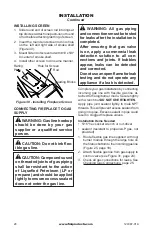
Page 20: ...g DQG FRQQHFWLRQV PXVW EH WHVWHG IRU OHDNV DIWHU WKH LQVWDOODWLRQ LV FRPSOHWHG After ensuring that gas valve LV RQ DSSO D FRPPHUFLDO OHDN detection solution to all con QHFWLRQV DQG MRLQWV I EXEEOHV DSSHDU OHDNV FDQ EH GHWHFWHG and corrected R QRW XVH DQ RSHQ ÀDPH IRU OHDN testing and do not operate any DSSOLDQFH LI D OHDN LV GHWHFWHG Complete your gas installation by connecting LQFRPLQJ JDV OLQH Z...

Page 21: ... Before installing module make sure all bat teries have been installed into the receiver and battery backup CAUTION Gloves should EH ZRUQ ZKHQ LQVWDOOLQJ PRGXOH LQWR UHSODFH 0HWDO HGJHV PD EH VKDUS 1 Plug module into J Box on the right side RI UHER ÀRRU VHH LJXUH 2 Connect shutoff valve of module to incom ing gas line see Connecting Fireplace to Gas Supply page 20 3 Connect wires from limit switch...

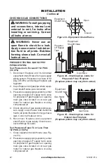
Page 22: ... main gas valve located on or near gas PHWHU IRU QDWXUDO JDV UHSODFH RU XVLQJ compressed air 4 Check all joints of gas supply piping sys tem Apply noncorrosive leak detection ÀXLG WR DOO MRLQWV XEEOHV IRUPLQJ VKRZ D leak Correct all leaks at once 5 Reconnect fireplace and equipment shutoff valve to gas supply Check recon QHFWHG WWLQJV IRU OHDNV Test Pressures Equal To or Less Than 36 N3D 1 Close e...

Page 23: ...IREPLACE GAS CONNECTIONS 1 Open equipment shutoff valve see Fig ure 33 page 22 2 Open propane LP supply tank valve for SURSDQH 3 UHSODFH RU PDLQ JDV YDOYH located on or near gas meter for natural JDV UHSODFH 0DNH VXUH FRQWURO NQRE RI UHSODFH LV LQ the OFF position 4 Check all joints from equipment shutoff valve to gas valve see Figure 34 or Figure 35 page 22 Apply noncorrosive OHDN GHWHFWLRQ ÀXLG ...

Page 24: ...or Frame Top Door Frame Smoke Shelf Ash Lip Ash Lip INSTALLING GLASS DOORS Spring clips have been installed but some adjustments may be needed Install the doors using the following steps 1 With bifold doors completely folded insert bottom pivot pin into pivot hole located near bottom corner of front face opening and swing door to vertical position making sure top pins slide into door track Door is...

Page 25: ...posi tion or press OFF on hand held remote 4 Fully open glass doors if installed 5 Remove center brick control cover 6 Turn equipment shutoff valve clockwise to the OFF position see Figure 41 Do not force DLW YH PLQXWHV WR FOHDU RXW DQ JDV Then smell for gas including near the ÀRRU I RX VPHOO JDV 6723 ROORZ in the safety information in column 1 If you don t smell gas go to the next step 8 Turn equ...

Page 26: ...lt in remote control receiver that allows the user to program the remote transmitter at any time during or after the installation of the burner 1 There is a switch located on the right side of the module that reads REMOTE OFF Figure 43 2 When the remote off switch is in the OFF position the burner will operate from the rocker switch or wall switch connected to the two BROWN wires on the module 3 W...

Page 27: ...e WR LQFUHDVH WKH ÀDPH WR SURSHU VL H VHH Figure 44 Do not remove the adjustment screw VHH Troubleshooting page 30 BURNER FLAME PATTERN XUQHU ÀDPHV ZLOO EH VWHDG QRW OLIWLQJ RU ÀRDW ing Flame patterns will be different from unit to unit and will vary depending on installation type and weather conditions I WKH YHQW FRQ JXUDWLRQ LV LQVWDOOHG LQFRUUHFWO ÀDPHV ZLOO OLIW RU JKRVW 7KLV FDQ EH GDQJHU RXV...

Page 28: ...VXOW LI WRR ODUJH D UH LV EXLOW RU LI FRPEXVWLRQ DLU gate is not completely open The following tips VKRXOG EH IROORZHG WR DVVXUH WKDW ERWK UH place and glass doors retain their beauty and IXQFWLRQ SURSHUO RWK ÀXH GDPSHU DQG JODVV GRRUV PXVW EH IXOO RSHQHG EHIRUH VWDUWLQJ UH 7KLV ZLOO SURYLGH VXI FLHQW FRPEXVWLRQ DLU DQG PDLQWDLQ VDIH WHPSHUDWXUHV LQ UHER Figure 47 Bi Fold Glass Doors Doors Fully C...

Page 29: ...osed to cold weather 4 Inspect joints to verify that no pipe section RU WWLQJ KDV EHHQ GLVWXUEHG DQG ORRV ened Check mechanical supports such as wall straps for rigidity OUTSIDE AIR AND DAMPER HANDLE OPERATION The damper handle which opens and closes the damper blade is located in the upper front IDFH RI WKH UHSODFH 3XVKLQJ WKH KDQGOH IRU ward and up through the keyway slot will free damper blade ...

Page 30: ...SLORW RUL FH 4 Low gas pressure 5 Kinked pilot line 6 Control valve is not opening 7 No power to unit or ignition module REMEDY 1 Check to see if you have gas supply and that equip ment shutoff valve is opened 2 Repeat lighting procedure several times to purge all air out of lines If after re peated attempts appliance does not light call for quali HG VHUYLFH DQG UHSDLU 3 Remove debris and dirt ins...

Page 31: ...ck the two plastic connectors that plug in the face of the gas FRQWURO YDOYH RQ UP WKH gas control valve is properly grounded to the module 1 Check electrical connec tions OHDQ DQG DGMXVW SLORW ÀDPH for maximum flame im pingement on thermopile 2 Have vent system inspect ed including termination cap Remove any restriction or obstruction 1 This is normal with most UHSODFHV I QRLVH LV H FHVVLYH FRQWD...

Page 32: ...aning and Maintenance page 28 RU UHSODFH EXUQHU RUL FH 2 Replace damaged burner 3 Replace gas control 1 Problem will stop after a few hours of operation 1 Turn gas control knob to LO position and let warm up for a minute 2 Operate burner until air is removed from line Have gas line checked by pro pane LP or natural gas company 3 Clean burner see Cleaning and Maintenance page 28 RU UHSODFH EXUQHU R...

Page 33: ...r does not light after pilot is lit REMEDY 1 Locate and correct all leaks see Checking Gas Connections page 22 1 Fireplacehasbeentestedforupto 40 mph winds However extreme conditions may occur See Light ing Instructions page 25 2 Check local propane LP or natu ral gas company 3 Clean pilot see Cleaning and Maintenance page 28 4 Locate and correct all vent con nections see Venting page 11 5 Replace...

Page 34: ...mproper venting or exces sive blockage 4 Excessive amounts of em bers and pan material OBSERVED PROBLEM Gas odor even when gas control valve is off Gas odor during combustion Glass soots Dark residue on logs or inside RI UHSODFH REMEDY 1 Locate and correct all leaks see Checking Gas Con nections page 22 2 Replace control valve 1 Take apart gas tubing and remove foreign matter 2 Locate and correct ...

Page 35: ...WXUDO DV 2QO JQLWLRQ OHFWURQLF 0DQLIROG 3UHVVXUH Z F 0LQLPXP QOHW 6XSSO 3UHVVXUH Z F 0D LPXP QOHW 6XSSO 3UHVVXUH Z F 2UL FH 0 1 5DWLQJ WX KU DV 7 SH 1DWXUDO DV 2QO JQLWLRQ OHFWURQLF 0DQLIROG 3UHVVXUH Z F 0LQLPXP QOHW 6XSSO 3UHVVXUH Z F 0D LPXP QOHW 6XSSO 3UHVVXUH Z F 2UL FH 0 3 5DWLQJ WX KU DV 7 SH 3URSDQH 3 2QO JQLWLRQ OHFWURQLF 0DQLIROG 3UHVVXUH Z F 0LQLPXP QOHW 6XSSO 3UHVVXUH Z F 0D LPXP QOHW 6...

Page 36: ...www fmiproducts com 124387 01A 36 PARTS 02 6 9 9 1 9 1 21 20 5 6 7 10 9 11 12 13 16 17 15 14 8 24 23 3 2 22 4 25 18 19 27 26 ...

Page 37: ...0 23490SA Standoff 4 11 Fireplace Surround Assembly 1 12 109720 02 Clearance Spacer 6 13 117891 01 Fireplace Handle Bracket 4 14 20042 Outside Air Cover Plate 2 15 21171 Gas Conduit Cover 4 16 109752 01 Conduit One 2 17 109752 02 Conduit Two 2 18 Firebox Support 2 Firebox Support 1 19 Firebox Legs 2 20 Inner Dome Assembly 1 21 Smoke Shield 1 22 Damper Control Bracket 1 23 109457 03 Screen 36 2 109...

Page 38: ...www fmiproducts com 124387 01A 38 PARTS 02 8 02 6 0 1 3 0 1 3 1 0 1 3 Logs not shown for clarity 9 5 10 2 8 13 6 3 4 1 7 11 12 ...

Page 39: ...125068 01 Battery Backup 1 7 125067 01 Power Module 1 8 125064 01 Control Module 1 9 108368 01 Flex Line 3 8 x 30 1 10 14264 Brass Elbow 1 11 110118 01 Flared Fitting 1 12 901062 01 Brass Elbow 1 13 125673 01 Logset Assembly 36 1 125673 02 Logset Assembly 42 1 125673 03 Logset Assembly 50 1 PARTS AVAILABLE NOT SHOWN 112799 01 Ember Flakes Kit 1 26839 Rockwool 1 101142 01SA Lave Rock Kit 1 117501 0...

Page 40: ...www fmiproducts com 124387 01A 40 PARTS MODELS MODELS MKB SERIES Picture may vary from actual 1 6 4 8 7 3 2 5 7 7 7 8 9 Red Brick Page 41 Ivory Brick Page 42 ...

Page 41: ... Right Herringbone 42 Red 1 125457 01 Right Herringbone 50 Red 1 6 124220 01 Left Stacked 36 Red 1 124232 01 Left Herringbone 36 Red 1 125447 01 Left Stacked 42 50 Red 1 125435 01 Left Herringbone 42 Red 1 125459 01 Left Herringbone 50 Red 1 7 124134 01 Side Retainer 36 Included with Firebox 4 124134 02 Side Retainer 42 50 Included with Firebox 4 124134 04 Side Retainer 36 Stainless Included with ...

Page 42: ...50 Ivory 1 125455 02 Rear Herringbone 50 Ivory 1 5 124218 02 Right Stacked 36 Ivory 1 124230 02 Right Herringbone 36 Ivory 1 125445 02 Right Stacked 42 50 Ivory 1 125433 02 Right Herringbone 42 Ivory 1 125457 02 Right Herringbone 50 Ivory 1 6 124220 02 Left Stacked 36 Ivory 1 124232 02 Left Herringbone 36 Ivory 1 125447 02 Left Stacked 42 50 Ivory 1 125435 02 Left Herringbone 42 Ivory 1 125459 02 ...

Page 43: ...ontact your local propane LP gas supplier TECHNICAL SERVICE You may have further questions about installation operation or troubleshooting If so contact FMI PRODUCTS LLC at 1 866 328 4537 When calling please have your model and serial numbers of your heater ready You can also visit FMI PRODUCTS LLC s web site at ZZZ IPLSURGXFWV FRP ACCESSORIES NOTICE OO DFFHVVRULHV PD QRW EH DYDLODEOH IRU DOO UHSO...

Page 44: ...ealers of this product and or FMI PRODUCTS LLC who will provide original factory replacement parts Failure to use original factory replacement parts voids this warranty Travel handling transportation diagnostic material labor and incidental costs associated with warranty repairs unless expressly covered by this warranty are not reimbursable under this warranty and are the responsibility of the own...

Reviews: