DESCO WEST
- 3651 Walnut Avenue, Chino, CA 91710 • (909) 627-8178
DESCO EAST
- One Colgate Way, Canton, MA 02021-1407 • (781) 821-8370 • Website:
Desco.com
TB-3083
Page 2 of 5
© 2020 DESCO INDUSTRIES INC
Employee Owned
December 2020
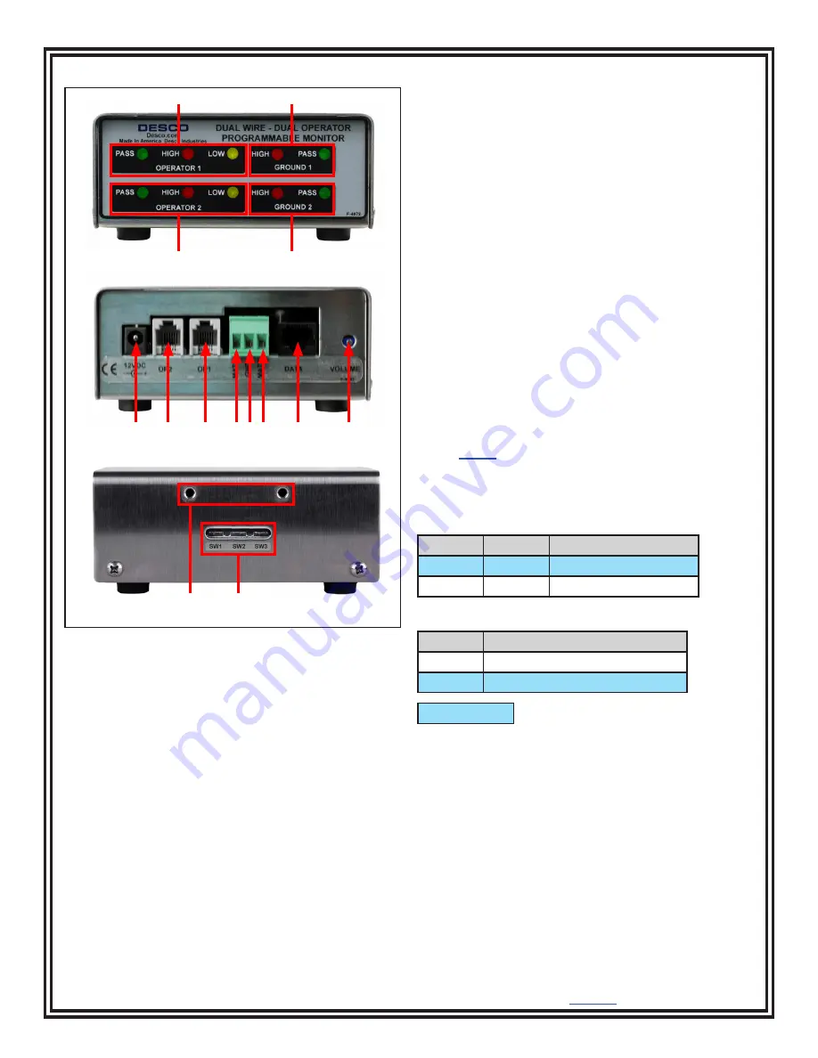
Features and Components
A. Operator 1 Status LEDs:
When the green LED is
illuminated, operator 1 is properly grounded. When the
LED is illuminated red or yellow and the alarm sounds,
operator 1 is not properly grounded.
B. Worksurface 1 Status LEDs:
When the green LED
is illuminated, worksurface 1 is properly grounded.
When the red LED is illuminated and the alarm sounds,
worksurface 1 is not properly grounded.
C. Operator 2 Status LEDs:
When the green LED is
illuminated, operator 2 is properly grounded. When the
LED is illuminated red or yellow and the alarm sounds,
operator 2 is not properly grounded.
D. Worksurface 2 Status LEDs:
When the green LED
is illuminated, worksurface 2 is properly grounded.
When the LED is illuminated red and the alarm sounds,
worksurface 2 is not properly grounded.
E. Power Jack:
Connect to the included 12VDC power
adapter.
F. Operator 2 Remote Jack:
Connect to the black
operator remote cable.
G. Operator 1 Remote Jack:
Connect to the white
operator remote cable.
H. Monitored Mat 1 Terminal:
Monitors a worksurface
mat for proper dissipative resistance and static charges.
Connect the white mat monitor cord here.
I. Ground Terminal:
Common ground point for the
monitor. Connect to the green and yellow monitor
ground cord.
J. Monitored Mat 2 Terminal:
Monitors a worksurface
mat for proper dissipative resistance and static charges.
Connect the black monitor cord here.
K. Data Output:
For manufacturer use only.
L. Alarm Audible Adjustment:
Turn the trimpot
counter-clockwise to increase the audible alarm volume
and clockwise to decrease it.
M. Mounting Holes:
8-32 PEM nuts are located on the
left and right sides of the monitor for pairing with the
Desco
19663
Mounting Brackets.
N. Operator Setting Switches:
Toggles the monitor’s
settings for operator test voltage and high test limit.
Switches 1 and 2 control the operator test voltage.
Switch 1 Switch 2 Operator Test Voltage
RIGHT
LEFT
5V
LEFT
RIGHT 8V
Switch 3 controls the operator HIGH test limit.
Switch 3 HIGH Limit Resistance
RIGHT
10 megohms (1 x 10⁷ ohms)
LEFT
35 megohms (3.5 x 10⁷ ohms)
default setting
Figure 2. Dual-Wire Dual Operator Monitor features and
components
A
C
B
D
E
F
G
H I J
K
L
FRONT VIEW
BACK VIEW
LEFT-SIDE VIEW
M
N


