14
107435
VENT-FREE PROPANE/LP PEDESTAL STOVE
For more information, visit www.desatech.com
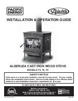
Figure 23 - Pilot
7.
Keep control knob pressed in for 30
seconds after lighting pilot. After 30
seconds, release control knob.
• If control knob does not pop out when
released, contact a qualified service
person or gas supplier for repairs.
Note:
If pilot goes out, repeat steps
3 through 7, pages 13 and 14. This
heater has a safety interlock system.
Wait one (1) minute for system to
reset before lighting pilot again.
8.
Turn control knob counterclockwise
C-clockwise
to desired heating level. The
burners should light. Set control knob
to any heat level between HI and LO.
TO TURN OFF GAS
TO APPLIANCE
Shutting Off Heater
Turn control knob clockwise
Clockwise
to
the OFF position.
Shutting Off Burners Only (pilot
stays lit)
Turn control knob clockwise
Clockwise
to
the PILOT position.
THERMOSTAT CONTROL
OPERATION
The thermostat control knob can be set to
any comfort level between Hi and Lo. The
thermostat will gradually modulate the heat
output and flame height from higher to
lower settings, or pilot, in order to maintain
the comfort level you select. The ideal com-
fort setting will vary by household depend-
ing upon the amount of space to be heated,
the output of the central heating system, etc.
OPERATING
HEATER
Continued
INSPECTING
BURNERS
Check pilot flame pattern and burner flame
patterns often.
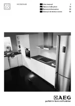
PILOT FLAME PATTERN
Figure 24 shows a correct pilot flame pat-
tern. Figure 25 shows an incorrect pilot flame
pattern. The incorrect pilot flame is not touch-
ing the thermocouple. This will cause the
thermocouple to cool. When the thermo-
couple cools, the heater will shut down.
If pilot flame pattern is incorrect, as shown
in Figure 25
• turn heater off (see To Turn Off Gas to
Appliance)
• see Troubleshooting, pages 16 through 18
Figure 24 - Correct Pilot Flame Pattern
Figure 25 - Incorrect Pilot Flame Pattern
Thermocouple
Pilot Burner
Pilot Burner
Thermocouple
CAUTION: Do not try to adjust
heating levels by using the equip-
ment shutoff valve.
Thermocouple
Pilot Burner
Light your gas appliance with the blower
off. Turn the blower on to deliver heated
air at the top louvers. The blower fea-
tures a variable control which allows you
to select the speed you desire.
If using the GA3650TA Blower Accessory:
In the ON position, the blower will start
when the thermostat senses a sufficient
increase in firebox temperature (approxi-
mately 10 to 20 minutes depending on
heat setting).
Note:
Your gas stove and
thermostat blower will not turn on and
off at the same time. The stove may run
for several minutes before the blower
turns on. After the heater modulates to
the pilot position, the blower will con-
tinue to run. The blower will shut off
after the firebox temperature decreases.
Note:
It is safe to operate stove with
blower turned off. However, the blower
helps distribute heated air from the stove.
Note:
Periodically check the louvers of
the firebox and remove any dust, dirt, or
other obstructions.
OPERATING
OPTIONAL BLOWER
ACCESSORY
1.
Follow steps 1 through 5 under Light-
ing Instructions, page 13.
2.
Depress control knob and light pilot
with match.
3.
Keep control knob pressed in for 30
seconds after lighting pilot. After 30
seconds, release control knob. Now
follow step 8 in column 1.
MANUAL LIGHTING
PROCEDURE
Note:
Selecting the Hi setting with the
control knob will cause the burners to
remain fully on, without modulating down
in most cases.
Continued