background image

12

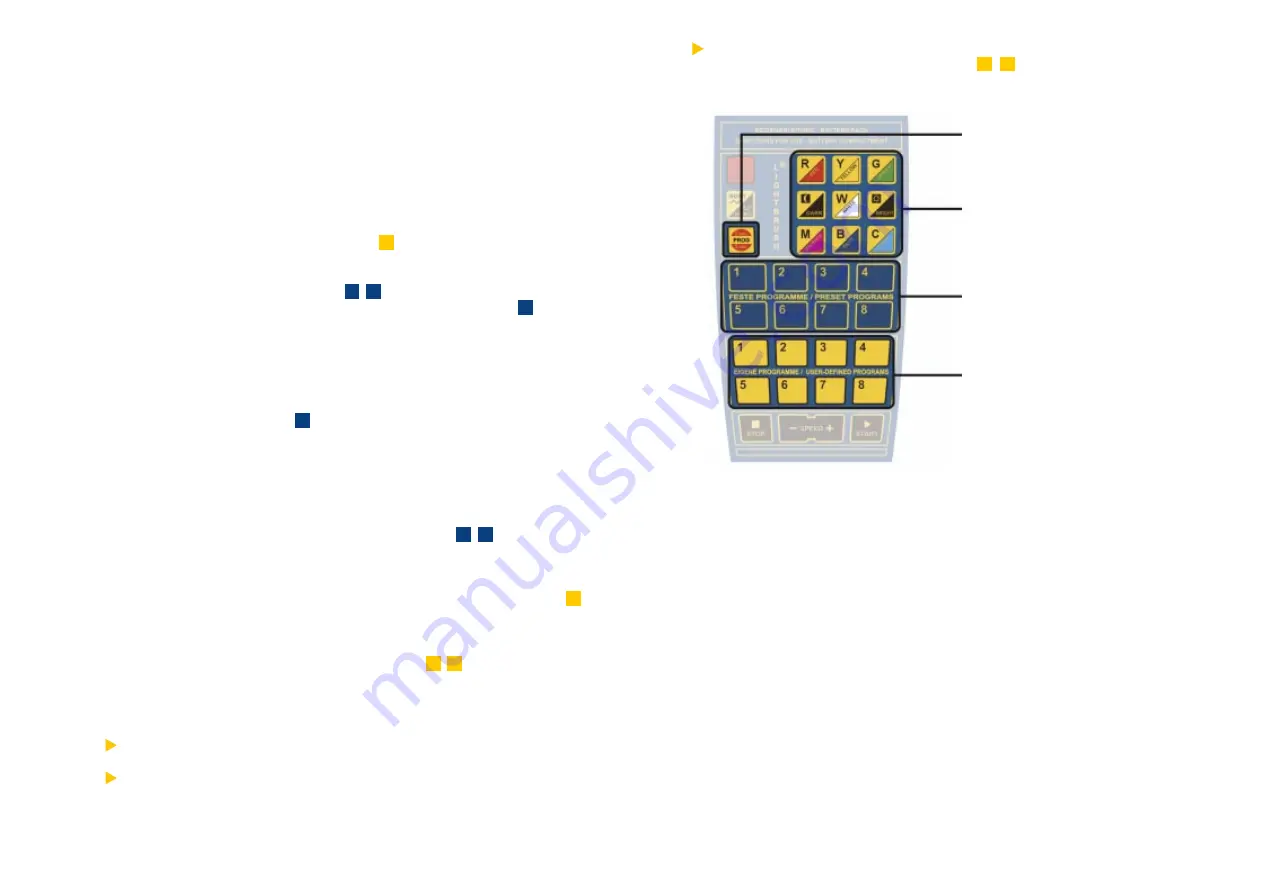
Use the blue buttons to access

the individual scenes of your

colour change program.

Use the yellow buttons to save

up to 8 of your own colour

change programs.

Use the „

PROGRAMM

“ button to

access the programming. To

activate it, hold the button for

approx. 3 seconds.

The Colour Control Field

Colours can be mixed easily following the colour palette concept:

Button „

R

“ (red): part of red light will be increased.

Button „

Y

“ (yellow): part of yellow light will be increased.

Button „

G

“ (green): part of green light will be increased.

Button „

DARK

“: brightness will be decreased.

Button „

BRIGHT

“: brightness will be increased.

Button „

W

“ (white): part of white light will be increased.

Button „

M

“ (magenta): part of pink light will be increased.

Button „

B

“ (blue): part of blue light will be increased

Button „

C

“ (cyan): part of green-blue light will be increased

User-defined programs will be overwritten automatically when you assign a

new program to a place (

yellow

 buttons from  1 - 8  ) that is already “occupied”

by an old program.

Modification Of User-Defined Programs:

Any colour change program can be modified during operation by the colour control

functions of your remote control (see: „Modification of Preset Programs“, p. 10).

11

2. Creating Custom Colour Sequences:

UIn order to adapt the colour light system to individual requirements, it is possible

to 

create and store user-defined colour change programs

. Therefore you can

define step by step every single scene of your program. Up to 8 different user-

defined programs can be stored and assigned to the yellow buttons of the remote

control. The programs can be recalled at any time, even after a power failure

(memory function!). Please follow the instructions below:

Step 1: Push the button „

PROGRAMM

“ for approx. 3 seconds to enter the

programming mode.

Step 2: Push one of the 

yellow

 buttons (eg.  

1

  ) in order to assign your program

to it. Later you can recall your program by pushing it.

Step 3: Using the 

blue

 buttons (from  

1

 - 

8

 ) you can select a single scene of

your colour change program. Please press the 

blue

 button  

1


 to define

colour for the first scene.

Step 4: Adjust the colour of the first scene by the 

colour control functions

 of

your remote control. Only when you are satisfied with the selected colour

continue with the second scene…

Step 5: Press the 

blue

 button 

2

 , to define colour for the second scene of your

program.

Step 6: Adjust the colour of the second scene by the 

colour control functions

of your remote control. Only when you are satisfied with the selected

colour continue with the third scene…

Step 7: Select additional scenes with the 

blue 

buttons  

3

 - 

8

  and adjust the

colour for each single scene.

Step 8: Press the button „

PROGRAMM

“ to end programming mode. Now the

complete program can be recalled and started by the yellow button  

1

  .

Create other colour change programs following the instruction above. A maximum

number of 8 programs can be stored (

yellow

 buttons  

1

 - 

8   

).

Note:

During programming, previous scenes can be recalled by the 

blue

 buttons, in

order to test or adjust the colour of a previous scene.

A colour change program may consist of less than 8 scenes. Once you are

satisfied with the number of scenes, just press the button “

PROGRAMM

” to

end programming.

Colour Control Field

Summary of Contents for Lightbrush RGB-Cube

Page 1: ...www derksen de contact our worldwide distribution network Manual Lightbrush rgb Module Lightbrush rgb Cube rgb Module 1500 rgb Module 1200 rgb Module 590 rgb Cube 230 V Version ...

Page 2: ... Cube Before switching the unit on for the first time please read these instructions and keep them in a safe place Table Of Contents Safety Precautions 2 Installation and Connection 3 Wall Floor or Ceiling Installation 3 Cable Connection and Routing 4 Plug Designations for Data Power Connections 4 LIGHTBRUSH Slave Unit Operation 5 LIGHTBRUSH Infrared Receiver 5 How to Configure Lightbrush for Even...

Page 3: ...echanical stress Data bus power cables routed over walls or ceilings must be secured at regular intervals of 2 m at least once per meter Cables routed on floors require additional protection against mechanical stress such as being stepped on Cables may be protected with ducts or tubes e g When routing cables always verify that there is no pull on the plugs 4 Installation and Connection Foor Wall o...

Page 4: ...e suffices to control 30 units You may exceed the maximum number of 30 units if you choose to connect lower power consumption slave modules such as LIGHTBRUSH Slave Module 590 to the LIGHTBRUSH master module If the power consumption of the slave units exceeds a total of 3200 VA and or if more than 30 units are to be connected to the master unit the system can be expanded with a LIGHTBRUSH Intermed...

Page 5: ...rol all functions at one glance 7 How to Configure Lightbrush for Evenly Distributed Illuminations For the colour illumination of an area certain aspects should be considered during planning installation the depth of the housing the transparency of the front pane the number of modules It is important that the 16 7 million colour shades of the LIGHTBRUSH RGB system have an even and colour homogenou...

Page 6: ...ng the speed of a running colour change program 1 Preset Programs Factory Settings After you switched the colour light system on you can immediately select one of the preset programs If you want to know how to create your own colour change program please proceed to chapter 2 Select one of the preset programs with the blue buttons on your remote control from 1 to 8 blue button 1 displaying all colo...

Page 7: ...igned to the yellow buttons of the remote control The programs can be recalled at any time even after a power failure memory function Please follow the instructions below Step 1 Push the button PROGRAMM for approx 3 seconds to enter the programming mode Step 2 Push one of the yellow buttons eg 1 in order to assign your program to it Later you can recall your program by pushing it Step 3 Using the ...

Page 8: ...th existing DMX standards Certified Quality The supplementary DMX 512 board of DERKSEN Lichttechnik has been certified under the terms of the German technical control board TÜV All components of the LIGHTBRUSH colour light system have the GS mark safety tested and the CE mark compliance with European safety standards Supplementary DMX 512 Board Connections Setting the DIP Switches at the DMX 512 C...

Page 9: ...e replacement lamp in place by turning it 90 The RGB module is now again ready for use LIGHTBRUSH Master Module 1500 Item No 09916200 Colour Light Module with Control Unit Type RGB 1500 Master W H D 1546 x 87 5 x 153 mm Housing Alu polished Weight 4 1 kg Power Input Plug 230 Volt 16 A Rated Power Consumption 180 VA Power Output 3200 VA Features Microprocessor for the control of 16 7 million colour...

Page 10: ...nd programmed with optional remote control 3 1200 mm RGB fluorescent lamps 36 W each data bus connector power connection to control slave mo dules Slave module connection up to 3200 VA depending on power supply LIGHTBRUSH Slave Module 1200 Item No 09916500 Colour Light Module without Control Unit Type RGB 1200 Slave W H D 1246 x 87 5 x 153 mm Housing Alu polished Weight 3 5 kg Rated Power Consumpt...

Page 11: ...sh de LIGHTBRUSH Slave Modules LIGHTBRUSH Slave Columns LIGHTBRUSH Master Module or Column All LIGHTBRUSH Systems can be combined with each other Safety All LIGHTBRUSH Systems have the following test certificates F geprüfte Sicherheit EN 60598 EN 61547 Interference Resistance EN 50081 1 Emission Date of Issue September 2003 Copyright 2003 by DERKSEN Lichttechnik GmbH ...

Reviews: