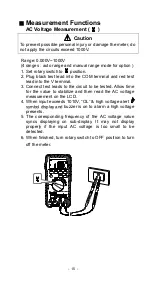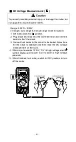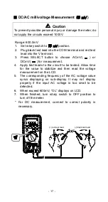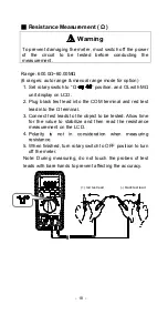
- 20 -
■
Diode Tests (
)
1. Set rotary switch to
“ Ω
” position.
2. Press SELECT button to choose the Diode Test mode,
OL
and
symbol display on the LCD.
3. Plug black test lead into the COM terminal and red test
lead into the
terminal.
4. Connect test leads to the diode and allow time for the
value to stabilize and then read the diode measurement
on the LCD.
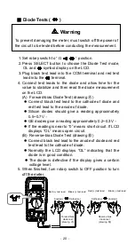
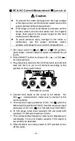
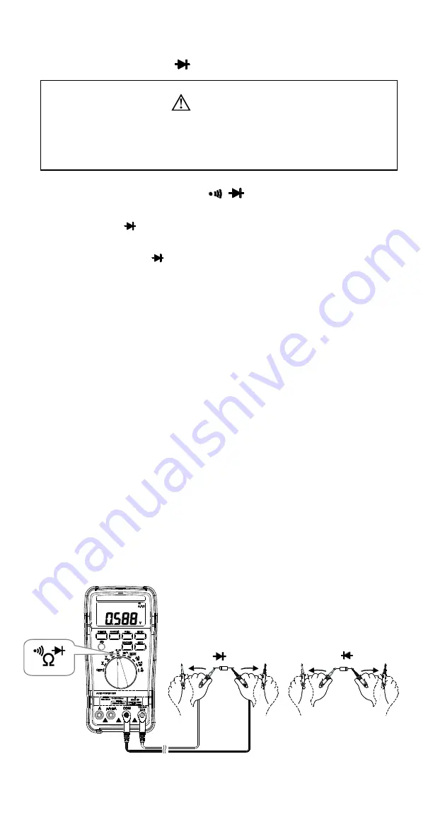
(A) Forward-bias Diode Test (drawing
Ⓐ
)
⚫
Connect black test lead to the cathode of diode and
red test lead to the anode of diode.
⚫
Silicon diodes should give a reading approximately
0.5~0.7V
。
⚫
GE diodes give a reading approximately 0.2~0.3V
。
⚫
If
the reading is near to “0” means short circuit. If LCD
displays “OL” means open circuit.
(B) Reverse-bias Diode Test (drawing
Ⓑ
)
⚫
Connect black test lead to the anode of diode and red
test lead to the cathode of diode.
⚫
Normally the LCD displays “OL” indicating that the
diode is in good condition.
⚫
The diode is defective if the display gives a certain
voltage level.
5. When finished, turn rotary switch to OFF position to turn
off the meter.
Anode(+)
Cathode(-)
Forward bias
diode test
(drawing
Ⓐ
)
Reverse bias
diode test
(drawing
Ⓑ
)
Black (-) test lead
Red (+) test lead
Black (-) test lead
Red (+) test lead
Cathode(-)
Anode(+)
Warning
To prevent damaging the meter, must switch off the power of
the circuit to be tested before conducting the measurement.
Summary of Contents for DE-5003
Page 2: ...31...


