background image

12

DEPA

®

 Air Operated Diaphragm Pumps

n

  Fasten the lifting tackle so that the    

  pump can be safely lifted.

n

  For pumps DH40-TP/TPL please use 

the corresponding lifting eye. For pumps 

DH50-TP/TPL please use the available 

notches.

Danger! 
In order to avoid slipping of the 
sling the rope must be crossed 
over at the hook (Fig. 1).

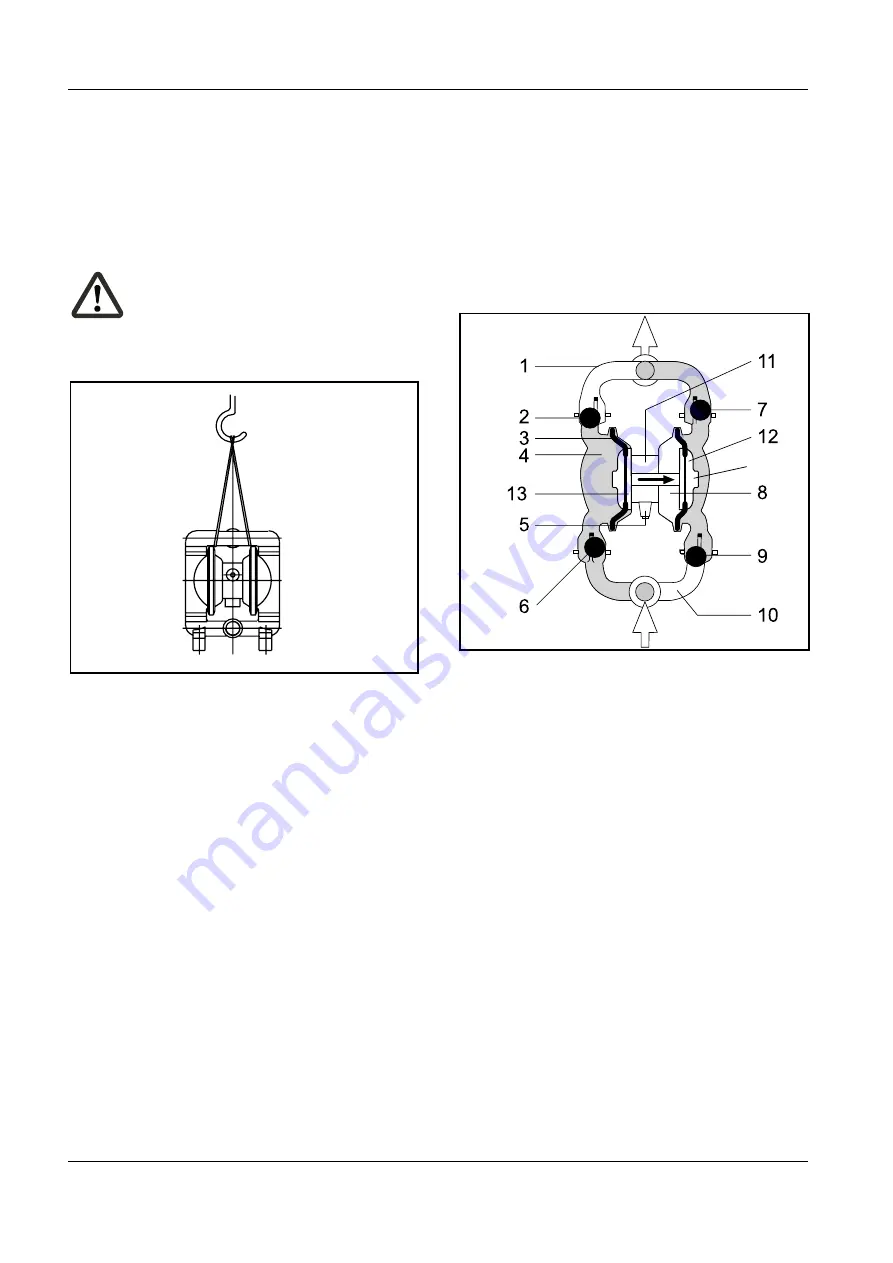
Fig. 1: Transport of pump

Be careful when unpacking the pump and 

proceed as follows:


Check the packaging material for trans-

port damage.

  Take the pump carefully out of the pack-

aging material.

  Check the pump for visual damage.

  Remove the plugs from all pump ports.

  Check seals and fluid lines for damage.

The following points must be strictly ob-

served when preparing the pump for stor-

age:

1  Discharge manifold
2  Top valve ball
 

(closed during suction)

3 Diaphragm
4  Pump chamber
5 Silencer
6  Bottom valve ball
 

(opened. Medium flows into chamber)

7  Top valve ball
 

(open. Product is pressed out)

8  Air chamber
 

(the drive air displaces the medium 


via the diaphragm and at the same time 


pulls back the second diaphragm)

9  Bottom valve ball 
 

(closed during delivery)

10  Suction socket
11  Air control unit
12  Outer piston
13  Inner piston 
14  Diaphragm, in the case of nopped E4

®


      without outer diaphragm plate

Fig. 2: Design of pump

  Store the pump in a dry place.

  Thoroughly clean used pumps before 

storage.

  Do not subject stored pumps to ex-

treme temperature fluctuations.

1.3  

Principle of function

14

Summary of Contents for DH 40-TP

Page 1: ...1 DEPA Air Operated Diaphragm Pumps www depapumps com www cranecpe com Air Operated Diaphragm Pumps Operating and Installation Instructions Installation Operation and Maintenance BA DL GB 01 19...

Page 2: ...rial number see identification plate in the version delivered by us is in compliance with the following applicable regulations EC Directive Machinery Directive 2006 42 EC Harmonized standards DIN EN 8...

Page 3: ...ited until it has been determined that the machine into which the above specified machine shall be incorporated meets the machinery directive 2006 42 EC Pay attention to the installation instructions...

Page 4: ...es Start up valve service unit clamping adapter mobile unit vehicle fluidisation system ball lifter needle valve level control collecting pan suction lance high performance silencer suction and pres s...

Page 5: ...FKM EPDM grey Accessories Needle valve level control mobile unit vehicle fluidisation system collecting pan suction lance high performance si lencer ball lifter suction and pressure hose Installed el...

Page 6: ...egulations EU Directive Directive 2014 34 EU for equipment intended for use in poten tially explosive environments Conformity assessment method Pump and accessories Equipment group II category 1G expl...

Page 7: ...s PTFE stainless steel 316L 1 4404 304 1 4301 EPDM grey O rings FKM FEP coated in the design delivered by us are in compliance with the following applicable regulations EU Regulations VO 2023 2006 und...

Page 8: ...al SS PL Diaphragm materials EPDM NBR electr conductive PTFE compound Valve ball materials EPDM NBR and PTFE only for size 15 in the version delivered by us comply with the following relevant regulati...

Page 9: ...fore commissioning 19 3 2 Design and arrangement of connecting lines 19 3 3 Placement and possible installations of the pump 20 3 4 Foundations 21 3 5 Connection of the air supply line 21 3 6 Connecti...

Page 10: ...w clamp bands 32 6 0 Troubleshooting 33 7 0 Active pulsation damper 35 7 1 Principle of function 35 7 2 Recommended installation schematic 35 7 3 Pulsation damper with diaphragm breakage monitoring 36...

Page 11: ...the pump mainly depend on correct installation correct commissioning and correctly performed maintenance and repair work Enquiries concerning service spare parts or repairs should be addressed to the...

Page 12: ...fluid lines for damage The following points must be strictly ob served when preparing the pump for stor age 1 Discharge manifold 2 Top valve ball closed during suction 3 Diaphragm 4 Pump chamber 5 Sil...

Page 13: ...e same time valve ball 2 is fixed in end position by the vacuum The left hand pump chamber is thus completely filled with product grey After switching of the control valve air flows into the left hand...

Page 14: ...g you should observe the temperature limit 1 4 2 Control air Max operating pressure see table 2 DEPA Air Operated Diaphragm Pumps are not subject to the pressure equipment directive acc to article 1 p...

Page 15: ...sion is 5 bar Maximum operating pressure for SLV SUV and UEV pumps in combination with EPDM grey elastomers is 5 bar Lifetime of the diaphragm reduces with increased temperature i e at 50 oC the lifet...

Page 16: ...ps with protective covering and guards these must be properly assembled again before restarting In case of deficiencies adversely affecting the safety the pump must be shut down im mediately and relia...

Page 17: ...Warning against caustic sub stances 2 8 Maintenance and repair work Maintenance and repair work must solely be carried out by qualified and specially in structed persons This applies particularly for...

Page 18: ...be assured that these parts will not start to move while work is in progress 2 9 Personal protective outfit You should always wear protective clothing suitable for the job in particular for cleaning m...

Page 19: ...ation Valves or spools must be installed as close as possible to pressure port This also applies for T fittings with valve for bypass control or pressure relief valves pressure gauges flow control val...

Page 20: ...installed to compensate any elongation of the pipes caused by temperature increase Note It is recommended to install flexible shape and pressure resistant hoses or 1 2 3 4 5 3 6 4 7 7 Luft versorgung...

Page 21: ...pipes to DEPA pumps equipped with cylindri cal female thread shortly signed G stan dard version ISO 228 G fittings with either cylindrical male thread none sealing wit hin the thread or fittings with...

Page 22: ...3 10 Pump on drum DEPA pumps of type DF can be directly mounted on drums or containers For simple emptying mount the pump with an adapter on the container Complete emptying of the container requires t...

Page 23: ...in 2 13 and 10 0 10 4 in it s present form of the operating manual have to be applied DHxx FA in custom design with control block for external air control 4 0 Operation 4 1 General After correct conn...

Page 24: ...e With a defective diaphragm product will en ter into the air chamber where it is detected by the integrated sensor When pumping conductive product the conductivity meas urement will measure a current...

Page 25: ...revents the settlement of soilds or chemical attacks and thus the destruction of the diaphragms when restarting 4 13 Taking out of service The pump stops when cutting off the air supply Since the valv...

Page 26: ...Replacement of diaphragms valve seats and valve balls Depending on the application air operated diaphragm pumps can be delivered with various elastomer materials The following materials are available...

Page 27: ...g 9 On the polished high grade steel ver sions DB DH unscrew the milk pipe fitting Remove the pump chambers Loosen the outer diaphragm plate and take it off with the diaphragm Fig 10 On plastic pumps...

Page 28: ...ate Fig 12 Disassembling the air chambers Fig 14 Installation of nopped E4 diaphragm Fig 15 Assembly of second pump chamber Fig 9 Opening the clamp bands Fig 8 Removing suction and pressure ports Fig...

Page 29: ...iaphragm takes place by means of indexing disc and set screw without the diaphragm plate After the set screw is threaded the diaphragm is to be screwed onto the plunger and tightened by hand 5 3 1 4 R...

Page 30: ...ss in the bore the O rings must not be pushed past the recess For this purpose an O ring is pushed over the bushing the bushing is then inserted into the bore with the side without O ring and pressed...

Page 31: ...e balls is done in reverse order of the above Information for the material can be found in Section 5 3 1 1 Fig 21 Pulling out the diaphragm with piston rod Fig 22 DH pump with interior control valve R...

Page 32: ...en in the exploded view Assemble the gasket so that the air sup ply bore remains open applies also for assembly of the air chambers Check air filter and muffler for clogging replace if necessary Durin...

Page 33: ...de worn Muffler clogged Air inlet filter clogged Insufficient air supply Pipelines blocked Viscosity too high Icing of the control valve Valve ball on suction side blocked Diaphragm cracked Diaphragm...

Page 34: ...ked Diaphragm not centred during assembly Large solids in product Compressed air opened with a shock Valve ball and seat leaking Pump completely dry Control valve worn Excessive feed on the suction si...

Page 35: ...irectly on the discharge manifold of the pump 7 2 Recommended installation schematic Pulsation dampers can be mounted in any position as long as there are not intentions to install diaphragm breakage...

Page 36: ...must not be installed horizontally they must be vertically installed as otherwise the function of the diaphragm monitoring system is not assured see sketch 4 7 4 Active pulsation damper with DEPA nop...

Page 37: ...re parts or accessories can have a neg ative effect on design features of the air op erated diaphragm pump and thus adversely affect its operation For damage caused by the use of non genuine spare par...

Page 38: ...lat gasket air chamber control block and con trol block cover exterior valve 51Q 2 not type SS Shaft bearing 64 2 Shaft bearing 64 1 Glide ring O ring 65 1 Nom inal width 15 2 Qty O Ring valve housing...

Page 39: ...Spare part kit type M Spare part kit type A R 19 23 25 31 32 50 13 90 11 21 30Z 01 80 77 51 2 51 3 51 1 69 45 65 2 64 02 25 65 1 30 47 46 23 25 70 23 78 79 31T R 78 only DL50 80 SS HS DL25 40 SS Q onl...

Page 40: ...part kit group G P Spare part kit type SU U R 25 11 18 24 23 27 10 90 14 21 31T 30TR 28 31 42 32 30 45 77 70 69 46 51 66 64 41 50 01 681 65 43 36 40 39 38 37 47 19 16 29 02 70 69PQ 64 65 01Q 05Q 50 6...

Page 41: ...aphragm Pumps Spare part kit X R 30 19 25 16 32 71 51 69 77b 77a 50 70 14 21 33 22 65 45 10 11 23 01 64 24 20 02 f r DH25 40 gilt for DH25 40 applies 50 51 2 69 77 64 65 51 3 51 1 02 25 24 26 20 25 70...

Page 42: ...ainless steel R R Stainless steel DB H R NBR steel core Y EPDM steel core W EPDM grau X with steel core PTFE steel core Z NRS steel core V Hytrel H DEPA nopped S4 S noppedE4 NRS 5 noppedE4 NBR 1 noppe...

Page 43: ...interior fittings 7 Table 6 max particle sizes Pump size Pump type DH SS 15 25 40 50 80 Particle size mm 5 8 11 13 18 10 1 2 Usage instructions When using the pump in zone 0 only media with a minimum...

Page 44: ...components the manu facturer s own declaration of conformity must be observed 10 1 5 1 The level control Earthing must be provided when a level control is installed 10 2 Equipment category 2 see 3 11...

Page 45: ...EX area to a work area Pumps intended for use in po tentially explosive environments must always be kept free of dust deposits 11 0 Tightening torques Tightening torques series L size 25 80 Pos 7 Pos...

Page 46: ...ber Pump chamber Pos 2 Pos 3 Pos 4 Pos 5 Flange Pos 7 DH25 UE 50 Nm 8 Nm 90 Nm 20 Nm 25 Nm DH40 UE 50 Nm 8 Nm 90 Nm 20 Nm 25 Nm DH50 UE 85 Nm 8 Nm 150 Nm 39 Nm 49 Nm Pump size Suction Discharge Air in...

Page 47: ...Pump size Suction Discharge Air inlet Air valve Piston Air chamber Clamp band manifold Pos 1 Pos 2 Pos 3 Pos 4 Pos 5 Pos 7 DL25 M 25 Nm 50 Nm 8 Nm 70 Nm 20 Nm max 23 Nm DL40 M 25 Nm 50 Nm 8 Nm 90 Nm...

Page 48: ...70 Nm 2 5 Nm 8 Nm DL40 P 25 Nm 50 Nm 8 Nm 90 Nm 2 5 Nm 10 Nm DL50 P 49 Nm 85 Nm 8 Nm 150 Nm 5 5 Nm 12 Nm DL80 P 49 Nm 85 Nm 8 Nm 150 Nm 5 5 Nm 15 Nm Tightening torques series PT size 15 80 drawing se...

Page 49: ...hamber rod diaphragm cover Centre block Pos 1 Pos 2 Pos 3 Pos 4 Pos 4 Pos 6 Pos 7 DH50 P 35 Nm 85 Nm 8 Nm 150 Nm 5 5 Nm 12 Nm Tightening torques series M Type DH FA SA SS Size 15 Pump size Suction Dis...

Page 50: ...7 Pos 4 Pos 1 Pos 6 Pos 7 Pos 3 Pump size Suction Discharge External Piston rod Centre block Pump chamber manifold air valve cover Pos 1 Pos 3 Pos 4 Pos 6 Pos 7 DH25 FA 25 Nm 8 Nm 70 Nm 5 Nm 25 Nm DH4...

Page 51: ...TL 5 Nm 50 Nm 1 Nm 2 5 Nm 6 Nm Tightening torques series P type DH PT TL size 15 40 Tightening torques series P Typ TP TPL size 15 50 R Pos 7 Pos 6 Pos 1 Pos 6 Pos 4 Pos 4 f r DH25 40 gilt beidseitig...

Page 52: ...ason we can only accept your shipment upon submission of our declaration of non objection including return number Upon our receipt of the filled out declaration of non objection you will receive a ret...

Page 53: ...oughly cleaned and decontaminated before shipment that the returned pump drive will not pose any dangers caused by bacteriological virological chemical or radioactive contamination that I am authorize...

Page 54: ...54 DEPA Air Operated Diaphragm Pumps...

Page 55: ...55 DEPA Air Operated Diaphragm Pumps...

Page 56: ...Process Flow Technologies GmbH P O Box 11 12 40 D 40512 D sseldorf Heerdter Lohweg 63 71 D 40549 D sseldorf Phone 49 211 5956 0 infoDus cranecpe com www depapumps com www cranecpe com We reserve the...

Reviews: