background image

Dentsply Sirona
Operating Instructions CEREC AC Connect

10 PC Diagnostic Tool

10.3 Test procedure

64 32 087 D3492
D3492.201.07.24.02    07.2018

79

Test result: Fail

An error was found on the PC-specific hardware. Replacing the PC
component or the PC may be required.
An image restore is not advisable.

1.

Check to find out which components did not pass the test.

2.

Write down the defective test number and, if available, the error
code and inform the technician of this as soon as possible.

3.

Carry out the appropriate steps in the chapter entitled
Troubleshooting  [→ 82] .

End 

"Customer Diagnostics"

 test

1.

Remove the PC diagnostic tool CD from the drive.

2.

Switch the PC off by briefly pressing the on/off key.

10.3.2

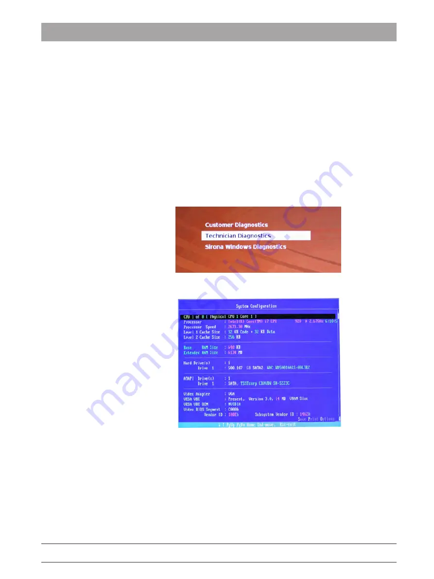
Technician Diagnostics

ü

You have started the 

"Technician Diagnostics"

 test and the

system configuration is displayed.

1.

Using the information in the system configuration, check whether
the system corresponds to the default settings. You can scroll up
and down using the arrow keys.
Tip: The test starts automatically after 3 minutes if you do not press
an arrow key.

2.

Press the 

"Esc"

 key on the keyboard.

Summary of Contents for CEREC AC

Page 1: ...New as of 07 2018 CEREC AC Connect With CEREC Omnicam Operating Instructions not valid for USA Canada English...

Page 2: ...the unit 12 4 1 3 General safety information 12 4 1 4 Movement and stability of the unit 13 4 1 5 Maintenance and repair 13 4 1 6 Modifications to the product 13 4 1 7 Accessories 14 4 1 7 1 Included...

Page 3: ...nal 37 7 Operation 40 7 1 Camera warm up time 40 7 2 Adjusting the CEREC Omnicam 40 7 3 Taking acquisitions with the CEREC Omnicam 41 7 4 Directing the camera 43 7 4 1 Occlusal scan 44 7 4 2 Buccal sc...

Page 4: ...3 8 3 Color calibration 66 8 4 Replacing the main fuse 70 8 5 Charge battery optional 71 8 6 Replace battery optional 72 9 Disposal 73 9 1 Disposal of the storage battery pack 74 10 PC Diagnostic Tool...

Page 5: ...amage Please read and follow these operating instructions carefully and Always keep them within easy reach To prevent personal injury or material damage it is important to observe all safety informati...

Page 6: ...ry and material damage please observe the warning and safety information provided in these operating instructions Such information is highlighted as follows DANGER An imminent danger that could result...

Page 7: ...action step 2 Second action step or Alternative action Result Individual action step Prompts you to do something See Formats and symbols used 7 Identifies a reference to another text passage and spec...

Page 8: ...see Disposal 73 Storage battery pack disposal symbol see Disposal of the storage battery pack 74 Storage battery pack recycling symbol see Disposal of the storage battery pack 74 The CEREC AC acquisit...

Page 9: ...D3492 D3492 201 07 24 02 07 2018 9 Symbols on the packaging Take note of the following symbols on the packaging Top Protect from moisture Fragile handle with care Temperature during storage and transp...

Page 10: ...for connected products Further products which are connected to this unit must also bear the CE mark Compliance Anyone creating or changing a medical electrical system through a combination with other...

Page 11: ...ot be used for any other purpose If the unit is used for any purpose other than the one mentioned above it may be damaged Intended use also includes compliance with these Operating Instructions and th...

Page 12: ...following the directions given in the present operating instructions 4 1 3 General safety information CAUTION Do not damage the monitor DO NOT touch the LCD screen with sharp or pointed objects If the...

Page 13: ...ng on a slippery surface and lateral forces are acting on it it may slide even though the wheel brakes are locked Always make sure that the unit s footprint is a flat nonskid surface 4 1 5 Maintenance...

Page 14: ...perated only with original Dentsply Sirona accessories or third party accessories expressly approved by Dentsply Sirona The user is responsible for any damage resulting from the use of non approved ac...

Page 15: ...st edition 2003 UL 60950 third edition 2000 UL 3101 1 Part 1 first edition 1993 They must be installed outside of the patient area a radius of 1 5 m surrounding the patient CAUTION Low voltages are ap...

Page 16: ...y 4 2 Safety labels Dentsply Sirona Operating Instructions CEREC AC Connect 16 64 32 087 D3492 D3492 201 07 24 02 07 2018 Heater plate CAUTION Risk of burns due to hot surface Never touch the heater p...

Page 17: ...rge ESD protective measures ESD protective measures include Procedures for preventing electrostatic charge build up e g air conditioning air moistening conductive floor coverings and non synthetic clo...

Page 18: ...is perceptible at 3 000 V or higher audible at 5 000 V or higher cracking crackling visible at 10 000 V or higher arc over The transient currents resulting from these discharges have a magnitude of 10...

Page 19: ...4 Wireless phone interference with equipment 64 32 087 D3492 D3492 201 07 24 02 07 2018 19 4 4 Wireless phone interference with equipment The use of mobile wireless phones in practice or hospital env...

Page 20: ...HUB switch The HUB switch must be located in the room where the acquisition unit is operated permanently installed be grounded via an additional ground wire Cross section of the protective ground wire...

Page 21: ...rated image processing High processing power due to state of the art processor Trackball Hand and foot controlled enter keys Wipe disinfectable membrane keyboard Hard disk DVD R W CD R W drive Etherne...

Page 22: ...W Combined drive GH24NS Hard disk 2TB 2 5 S ATA SSHD Network card Ethernet 10 100 1000 Mbit s on board WLAN card TP Link T6E Archer Sound card Realtek HD Audio onboard Graphics card AMD RX 470 Supply...

Page 23: ...ess of water Ordinary device without protection against ingress of water Pollution degree 2 Installation category Operating mode Continuous operation Battery backed operation for 6 minutes Storage bat...

Page 24: ...as UNIT 5 3 1 Electromagnetic emission The UNIT is intended for operation in the electromagnetic environment specified below The customer or user of the UNIT should make sure that it is used in such a...

Page 25: ...al mode voltage 2 kV common mode voltage The quality of the line power supply should be that of a typical commer cial or hospital environment Voltage dips short interruptions and variations of the pow...

Page 26: ...ipment bearing the following graphic symbol Remark 1 The higher frequency range applies at 80 MHz and 800 MHz Remark 2 These guidelines may not be applicable in all cases The propagation of electromag...

Page 27: ...nsmission frequency m 150 kHz to 80 MHz 80 MHz to 800 MHz 800 MHz to 2 5 GHz d 1 2 P d 1 2 P d 2 3 P 0 01 0 12 0 12 0 23 0 1 0 38 0 38 0 73 1 1 2 1 2 2 3 10 3 8 3 8 7 3 100 12 12 23 For transmitters w...

Page 28: ...complete 2 Check whether the product shows any visible signs of damage NOTE Damage during transport If the product was damaged during transport please contact your carrying agent If return shipment is...

Page 29: ...4 02 07 2018 29 6 4 Initial startup 6 4 1 Controls and functional elements Overview of the front panel A Monitor ON OFF switch H Center trackball button B Membrane keyboard I Left trackball button C C...

Page 30: ...32 087 D3492 D3492 201 07 24 02 07 2018 A Operating state LED B ON button Components of the Omnicam A Press detent to release D Camera windows B Mirror sleeve E Calibration set C Sapphire glass coate...

Page 31: ...perating Instructions CEREC AC Connect 6 Installation and startup 6 4 Initial startup 64 32 087 D3492 D3492 201 07 24 02 07 2018 31 Overview of rear side A Fuses C Power connection B Main switch I ON...

Page 32: ...02 07 2018 6 4 2 Operating state LED A Operating state LED B ON button LED not lit Acquisition unit is switched off at main switch LED lights up yel low Acquisition unit is switched on at main switch...

Page 33: ...k the plug connection you will damage the cable Never pull on the cable Slide the moving part of the plug in coupling upward on the CEREC AC Connect At the same time hold the camera connector in place...

Page 34: ...k panel NOTE Open with coin Use a coin to open the latch Turn counterclockwise 2 Remove the battery cover 3 Insert the battery into the battery compartment with the mounting screw and screw it down 4...

Page 35: ...tion may form and result in a short circuit Install the unit at room temperature Wait until the unit has reached room temperature and is absolutely dry for at least one hour The unit is dry and can be...

Page 36: ...on can be invoked with F1 or via the Help menu option NOTE Internet Explorer V 5 0 or higher must be installed on your system in order to use the online help function 6 4 8 Switching the units off NOT...

Page 37: ...nning in the battery powered mode this is indicated by a message displayed at the bottom of the screen It is accompanied by a rhythmic beep This beep changes to a continuous signal 30 seconds before t...

Page 38: ...r Following a double click on the symbol the following monitoring window opens The following information is displayed in the monitoring window Monitoring window Explanation Line voltage switched on an...

Page 39: ...il the PC shuts down A continuous signal is then sounded via the system loudspeaker The temperature monitor has two message thresholds The first message threshold is output as the message High in the...

Page 40: ...eater plate You can set the end temperature to which the camera heater warms the Omnicam mirror sleeve 1 In the software navigate to the system menu and click on the Configuration button 2 Click on th...

Page 41: ...htness The image brightness during the acquisition is controlled automatically so that there is always optimum image brightness largely independent of the distance between the CEREC Omnicam and the to...

Page 42: ...ich can be used to look around the patient s mouth 2 Remove the CEREC Omnicam from its holder As soon as the camera is pointed over a tooth or the gums data acquisition begins During the continuous da...

Page 43: ...the registration cannot be implemented the acquisition flow is suspended You are informed of this by means of a sound This is different to the sound emitted during successful acquisition You can adju...

Page 44: ...do so slowly move the CEREC Omnicam in the occlusal direction from the distal positioned tooth over the prepared tooth to the mesial positioned tooth With full jaw acquisitions the scan sequence is d...

Page 45: ...e approximal surfaces of the prepared tooth Move the CEREC Omnicam in the occlusal direction to the prepared tooth Acquire the approximal surfaces in the distal and mesial direction by using a wave mo...

Page 46: ...or to completing the registration This buccal scan should be carried out close up to the preparation To acquire sufficient geometry capture the teeth of the upper and lower jaw as well as 5 mm of the...

Page 47: ...quadrant and jaw The following scan regulation applies for the acquisition of a complete quadrant or jaw arch The first fourth quadrant is scanned up to the opposite second front tooth by moving the c...

Page 48: ...ly Tilt the camera by 45 in a palatinal direction oral and guide it from the distal to the mesial 2 Tilt the camera another 45 in a palatinal direction oral and move it in a distal direction 3 Tilt th...

Page 49: ...only tilted by 45 in a palatinal direction oral moving from the distal and back to the mesial to the front teeth 3 Once you have reached the area of the front tooth guide the camera 45 to the buccal...

Page 50: ...way from the line This cut must be completed during the ACQUISITION phase using the cutter 7 4 8 Completing measurements The exposures are complete 1 Click on the Next button The virtual model is calc...

Page 51: ...t out any areas that e g are located behind the model or are otherwise cut away from the line You are now in the ACQUISITION phase 1 Click on the tool wheel 2 Click on the Cut button The cursor change...

Page 52: ...e operator Dentsply Sirona would like to draw your attention to the fact that a so called retest repeat test must be carried out for the CEREC AC acquisition unit at least every three years In additio...

Page 53: ...bsorbent cotton gauze which is moistened with one of the cleaning agents listed in the Cleaning agents and disinfectants 52 section to disinfect the non critical contact surfaces of the CEREC AC such...

Page 54: ...ositions the ease of action of the ball can be set by selecting the corresponding detent position 8 1 5 CEREC Omnicam CAUTION If the CEREC Omnicam accidentally falls down check to make sure that the c...

Page 55: ...ing methods are available for cleaning the mirror sleeves Wipe disinfection for the camera and mirror sleeve 56 High level disinfection of the mirror sleeve 57 Hot air sterilization of the mirror slee...

Page 56: ...leeve while it is on the camera so that no dirt whatsoever can remain stuck and can harden on the surface of the mirror sleeve Use an absorbent cotton based gauze for this with water and neutral soap...

Page 57: ...is replaces the set with REF 63 46 907 The processes for both HLD sets can be found in the document CEREC camera care cleaning disinfection and sterilization available on our online portal for Technic...

Page 58: ...in order to ensure that no particle contamination or fluids penetrate the inside of the mirror sleeve The plug provides a waterproof seal for the mirror sleeve when attached correctly CAUTION Observe...

Page 59: ...02 07 2018 59 9 Insert the metal bracket with the metal sleeve 10 Place the cover on the container and leave the mirror sleeve in the disinfectant for at least 12 minutes CIDEX OPA The mirror sleeve...

Page 60: ...mirror sleeve with water from the mains while holding it with the bracket 13 Remove the bracket from the mirror sleeve carefully and slowly by pushing the bracket downwards Ensure that the mirror slee...

Page 61: ...the mirror sleeve 56 8 1 5 8 Hot air sterilization of the mirror sleeve NOTE Hot air sterilization and high level disinfection must not be combined The process for hot air sterilization is as follows...

Page 62: ...ition the CEREC Omnicam in the holder so that it can warm up for 15 minutes prior to the intraoral exposure Make sure that the holder has been disinfected 3 In the case of intraoral exposures with dis...

Page 63: ...aking stress or during first commissioning after storage in unheated or un air conditioned rooms temperature differences exceeding 30 C with temperature differences of over 15 C between the last calib...

Page 64: ...clockwise motion until it gently locks into place 4 Click on the OK button The measuring process starts The software prompts you to proceed to the next latching 5 Turn the screw counter clockwise unt...

Page 65: ...calibration process is continued Once the calibration is complete a message is displayed indicating this 3 Confirm the message by clicking the OK button The CEREC Omnicam is calibrated Error message...

Page 66: ...the Omnicam test tool on my cerec com CEREC SW 4 5 Shade Detection You can find the serial number of the Omnicam on the upper side on the optics tube see arrow E in the figure below This is only rele...

Page 67: ...es on the inside of the color calibration set it must be carefully removed using compressed air Switch on the color analysis 1 In the software navigate to the system menu and click on the Configuratio...

Page 68: ...al number printed on your color calibration set click on the Rescan QR Code button and scan the new QR code 4 Mount the color calibration set on the tip of the camera until it locks into place 5 Click...

Page 69: ...se has been reduced to less than 2 years can only be used for one year after the container has been opened Write the date that the container was opened on the container after Opened on ___________ usi...

Page 70: ...ct the power plug at the unit end before replacing the fuses NOTE Fuse type Use only fuses of the same type in the fuse module 230 115 D A B C A Voltage selection insert C Fuse module B Main fuses D W...

Page 71: ...e battery is permanently charged during operation on mains voltage This allows brief buffer operation after one hour of charging For a complete charge the battery must be charged without interruption...

Page 72: ...ry connector 1 Open the lower door on the back panel NOTE Open with coin Use a coin to open the latch Turn counterclockwise 2 Remove the battery cover 3 Unplug the battery connector 4 Unscrew the fast...

Page 73: ...In Germany To initiate return of the electrical device please send a disposal request to enretec GmbH You have the following options here Use the Returning an electrical device button under the eom m...

Page 74: ...to recycling if it becomes defective or reaches the end of its service life Recycling is performed via Sirona The storage battery pack is marked with the adjacent symbol Disposal of the storage batter...

Page 75: ...figuration before using the PC diagnostic tool If the configuration is set incorrectly the PC diagnostic tool will not recognize the hard drive and cannot check it The PC diagnostic tool then register...

Page 76: ...the technician in order to check the PC components Sirona Windows Diagnostics Windows Stress Test in order to test the PC at permanent load Tip If one of the following steps does not work further ste...

Page 77: ...board The test starts 10 3 Test procedure 10 3 1 Customer Diagnostics You have started the Customer Diagnostics test and the system configuration is displayed 1 Using the information in the system con...

Page 78: ...mpletion of the test press any key to go on to the test dialog Tip You can scroll to the individual test steps using the arrow keys The corresponding result is shown in front of each test step 4 To en...

Page 79: ...cian of this as soon as possible 3 Carry out the appropriate steps in the chapter entitled Troubleshooting 82 End Customer Diagnostics test 1 Remove the PC diagnostic tool CD from the drive 2 Switch t...

Page 80: ...mpletion of the test press any key to go on to the test dialog Tip You can scroll to the individual test steps using the arrow keys The corresponding result is shown in front of each test step 4 To en...

Page 81: ...ndows Diagnostics General The Sirona Windows Diagnostics test loads the PC specific components simultaneously over a long period of time This period of time is determined by the user As a result of th...

Page 82: ...found on the PC specific hardware Replacing the PC component or the PC may be required An image restore is not advisable 1 Check the Windows Stress Test window for those components that did not pass t...

Page 83: ...oo slow Replace the PC Test Keyboard Controller This test checks the proper function of the electrical circuit for the key board controller Replace the PC Test INT 1 The test tool checks the system in...

Page 84: ...es or other dirt 2 Check the SATA line between the PC and DVD drive 3 Check the power supply line between the PC and DVD drive 4 Replace the DVD drive 5 Check the SATA connection from the mainboard to...

Page 85: ...18 85 Test Test description condition Action if problems occur Test VGA RAM This test checks the graphics mem ory installed in the graphics card that is currently active Replace the graphics card Test...

Page 86: ...us load and inspection of the hard disk 1 Check the hard disk s SATA line 2 Check the hard disk s power supply 3 Exchange the hard drive including the hard drive cable Memory testing Continuous load a...

Page 87: ...themselves against data losses users should make backup copies of the data regularly 11 2 1 Creating burning a CD The Nero Multimedia Suite 10 Essentials program is installed on the acquisition unit f...

Page 88: ...roved by us may be used in this module Following a repair the seal supplied along with the spare parts must be affixed at the specified location A 11 4 Windows Update Windows Update is a service which...

Page 89: ...icon 36 Cleaning agents 53 Compliance 10 Conditions Operation 23 Storage 23 Transport 23 Customer service center 5 D Dimensions 24 Disinfectants 53 Disinfecting 53 Disposal of old electrical and elect...

Page 90: ...rrent 23 Rated line voltage 23 Relative humidity Operation 23 Storage 23 Transport 23 Repair 13 S Safety instructions 6 Sapphire glass 30 55 Scope of supply 28 Setting Trackball 54 Storage battery 71...

Page 91: ......

Page 92: ...be required due to technical improvements Sirona Dental Systems GmbH Sprache englisch Printed in Germany D3492 201 07 24 02 07 2018 Nr 125 755 Sirona Dental Systems GmbH Fabrikstr 31 64625 Bensheim G...

Reviews: