Denon PMA-1500AE Operating Instructions Manual Download Page 12

ENGLISH

• Speaker impedance

• When using speaker systems A and B separately, speakers

with an impedance of 4 to 16 

/ohms can be connected.

• When biwiring with biwireable speaker system, speakers

with an impedance of 4 to 16 

/ohms can be connected.

• Note that when using two sets of speaker systems together

(A + B), use speakers with impedance 8 to 16 

/ohms,

using speakers with an impedance other than between 8 to
16 

/ohms may cause damages.

Note that this unit is not equipped with a switch for
selecting the speaker system.  The A and B speaker output
terminals are connected in parallel.

• The protective circuit may be activated if speakers with

other impedances are connected.

• Be sure to connect the cords between the speaker terminals

and speaker systems with the same polarities (

<

to 

<

>

to

>

).  If not, the central sound will be weak and the position of

the different instruments will not be clear, diminishing the
stereo effect.

• When connecting the speakers, be sure that the core wires of

the speaker cords do not stick out from the terminals and
touch other terminals, each other or the rear panel.

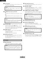
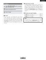
• Connecting the speaker cords

q

Peel off the sheathing from the end of the cord.

w

Twist the core wires.

e

Turn the speaker terminal counterclockwise to loosen it.

r

Insert the core wires entirely, then turn the terminal
clockwise to tighten it.

Protective Circuit

This set is equipped with a high speed protective circuit.
This circuit protects the internal circuitry from damage due
to large currents flowing when the speaker jacks are not
completely connected or when an output is generated by a
short circuit.  This protective circuit’s operation cuts off the
output to the speakers.  In such a case, be sure to turn the
power off and check the connections to the speakers.  Then
turn the power on again.  After muting for several seconds,
the set will operate normally.

NOTE:

Never touch the speaker terminals when the power is on.
Doing so could result in electric shocks.

Connecting the speakers

Connections

NOTE:

• Do not plug in the power supply cord until all connections are

completed.

• Be sure to connect the left and right channels properly.
• Insert the plugs securely.  Incomplete connections can result

in noise.

• Note that placing the pin plug cords next to power supply

cords or near power transformers may result in humming or
other noise.

• The PHONO input ter minals have an extr emely high

sensitivity, so avoid turning up the volume when no pin plug
cords are connected.  Doing so may result in induction
humming (booming) from the speakers.  When pin plug cords
are not connected, insert the included short-circuit pin plug.

Either tightly twist or terminate
the core wires.

Speaker cords

Speaker terminal

7

ENGLISH

Summary of Contents for PMA-1500AE

Page 1: ...PRE MAIN AMPLIFIER PMA 1500AE OPERATING INSTRUCTIONS BEDIENUNGSANLEITUNG MODE D EMPLOI ISTRUZIONI PER L USO INSTRUCCIONES DE OPERACION GEBRUIKSAANWIJZING BRUKSANVISNING...

Page 2: ...st ndares EN60065 EN55013 EN55020 EN61000 3 2 y EN61000 3 3 Siguiendo las provisiones de las Directivas 73 23 EEC 89 336 EEC y 93 68 EEC EENVORMIGHEIDSVERKLARING Wij verklaren uitsluitend op onze vera...

Page 3: ...det werden soll trennen Sie das Netzkabel vom Netzstecker D brancher le cordon d alimentation lorsque l appareil n est pas utilis pendant de longues p riodes Disinnestate il filo di alimentazione quan...

Page 4: ...m t nda ljus b r placeras p apparaten T nk p milj aspekterna n r du bortskaffar batteri Apparaten f r inte uts ttas f r v tska Inga objekt med v tskor s som vaser f r placeras p apparaten A NOTE ABOUT...

Page 5: ...ELLO ANTERIORE PANEL FRONTAL VOORPANEEL FRAMSIDA REAR PANEL R CKWAND PANNEAU ARRIERE PANNELLO POSTERIORE PANEL TRASERO ACHTERPANEEL BAKSIDA 1 0 i o y t r 2 u e q 3 w 4 5 6 7 9 8 0 1 ENGLISH DEUTSCH FR...

Page 6: ...rding 10 Copy from one tape to another 10 Troubleshooting 11 Specifications 12 Please check to make sure the following items are included with the main unit in the carton q Operating instructions 1 w...

Page 7: ...knob or connect components to the input terminals Muting of PRE OUT terminals and SPEAKER terminals The PRE OUT terminals and SPEAKER terminals include a muting circuit Because of this the output sign...

Page 8: ...ive or erratic if the infrared remote control sensor on the amplifier is exposed to strong light or if there are obstructions between the remote control unit and the sensor In case you operate a VCR T...

Page 9: ...the knob to the right If the volume on the left side is too low turn the knob to the left This will achieve an even balance on the left and right sides y VOLUME control knob This knob controls the ov...

Page 10: ...This switch is set according to the type of player cartridge to be used Set this switch to MM or MC according to the type of cartridge used on your turntable NOTE This terminal is used to reduce noise...

Page 11: ...o the OFF position after turning the power off from the remote control unit and then set back to the ON STANDBY position the PMA 1500AE is set to the operating mode AMP block FUNCTION button section U...

Page 12: ...Insert the core wires entirely then turn the terminal clockwise to tighten it Protective Circuit This set is equipped with a high speed protective circuit This circuit protects the internal circuitry...

Page 13: ...Power amplifier Subwoofer Power supply cord LINE OUT LINE OUT LINE OUT LINE IN LINE IN LINE IN REC LINE OUT PB SPEAKER SYSTEM BI WIRING When bi wiring with bi wireable speakers connect the mid and hig...

Page 14: ...mode in a few seconds 2 Checking connections POWER PHONES BASS TREBLE BALANCE VOLUME REC OUT SELECTOR INPUT SELECTOR P DIRECT SOURCE DIRECT MUTING TUNER PRESET DVD AUX CD TUNER TAPE 2 MD TAPE 1 CD R...

Page 15: ...the recording condition 2 Copy from one tape to another To copy from TAPE 1 CD R to TAPE 2 MD set the REC OUT SELECTOR knob to TAPE 1 1 2 To copy from TAPE 2 MD to TAPE 1 CD R set the REC OUT SELECTO...

Page 16: ...equipped with an output control Positions of instruments inverted for stereo sources Left and right speakers or input cords the inverted Check the left right connections 8 Booming sound produced when...

Page 17: ...0 84 V Input CD 125 mV 2 OVERALL CHARACTERISTICS SN Ratio IHF A Network PHONO input terminals short circuited MM 89 dB at 5 mV input input terminals short circuited MC 74 dB at 0 5 mV input SOURCE DI...

Page 18: ...Denon Brand Company D M Holdings Inc Printed in Japan 00D 511 4374 009 TOKYO JAPAN www denon com...

Reviews: