4
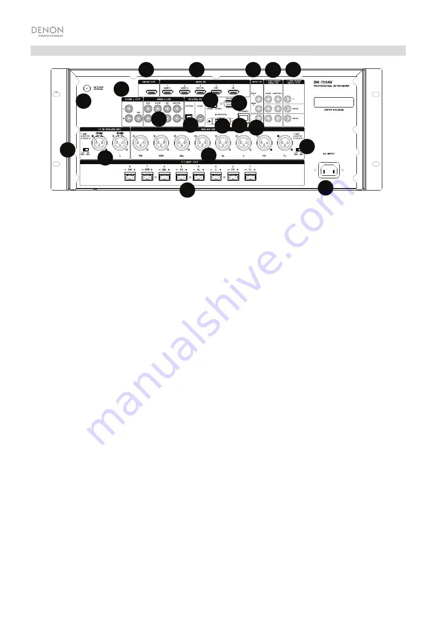
Rear Panel
1.
Digital Inputs:
Connect devices with coaxial and optical audio inputs here.
2.
Network Connector:
This connector is used to connect the unit to a LAN (local area network). The port is
used to remotely control the unit, to stream audio from a media server, or to connect to Internet radio.
3.
Composite Video Inputs:
Connect video outputs from a composite video device here.
4.
HDMI Inputs:
Use these
5 HDMI inputs to directly route the video and audio from a Blu-ray player, DVD
player to the HDMI output.
5.
HDMI Out:
Connect this HDMI output to a TV, projector, computer monitor, or DVR.
6.
Analog Audio Inputs:
Connect the audio output of your sound sources here.
7.
Serial Port:
This input lets you connect a host device (usually a computer) to DN-700AV. You can use the
host device to control DN-700AV via commands sent from it (using RS-232C serial communication).
8.
Video Out (Composite):
Connect this video output to the video input of another video source.
9.
Video Inputs (Component):
Connect the video inputs to the video output of another video source.
10.
Video Outputs (Component):
Connect the video outputs to the video input of another video source.
11.
FM Tuner Antenna:
Connect the included antenna here to get reception for FM radio sources.
12.
CD In:
Connect these
balanced XLR inputs to the output of a preamp or mixer.
13.
Input Level Setting Switch:
Adjust this to switch the audio input level to -10 dBv or +4 dBu.
14.
Balanced Outputs:
Connect these individual surround channel XLR outputs to the input of a mixer or
preamp.
15.
Balanced Output Level:
Adjust this to switch the surround channel XLR output level to -10 dBv or +4 dBu.
16.
Power Input:
Connect the included power cable here.
17.
Zone 2 Outputs:
Sends the audio signal from the
L/R and subwoofer output to another location.
18.
7.1 Amp Out:
Use these Euroblock outputs to send individual channels of the surround mix of the audio to a
speaker setup (75W per channel).
19.
Bluetooth Antenna:
The integrated antenna is used for Bluetooth reception.
20.
Firmware Update:
The “Service/Normal” switch is used to set the mode for the USB connection for the
firmware upgrade. For normal operation, this switch should be left in the Normal position.
7
10
8 9
11
12 13
14
15
16
17
18
6
4
5
1
2
3
7
10
10
8
9
11
11
12
12
6
4
5
1
2
3
13
13
14
14
15
15
16
16
17
17
18
18
19
19
20
20


