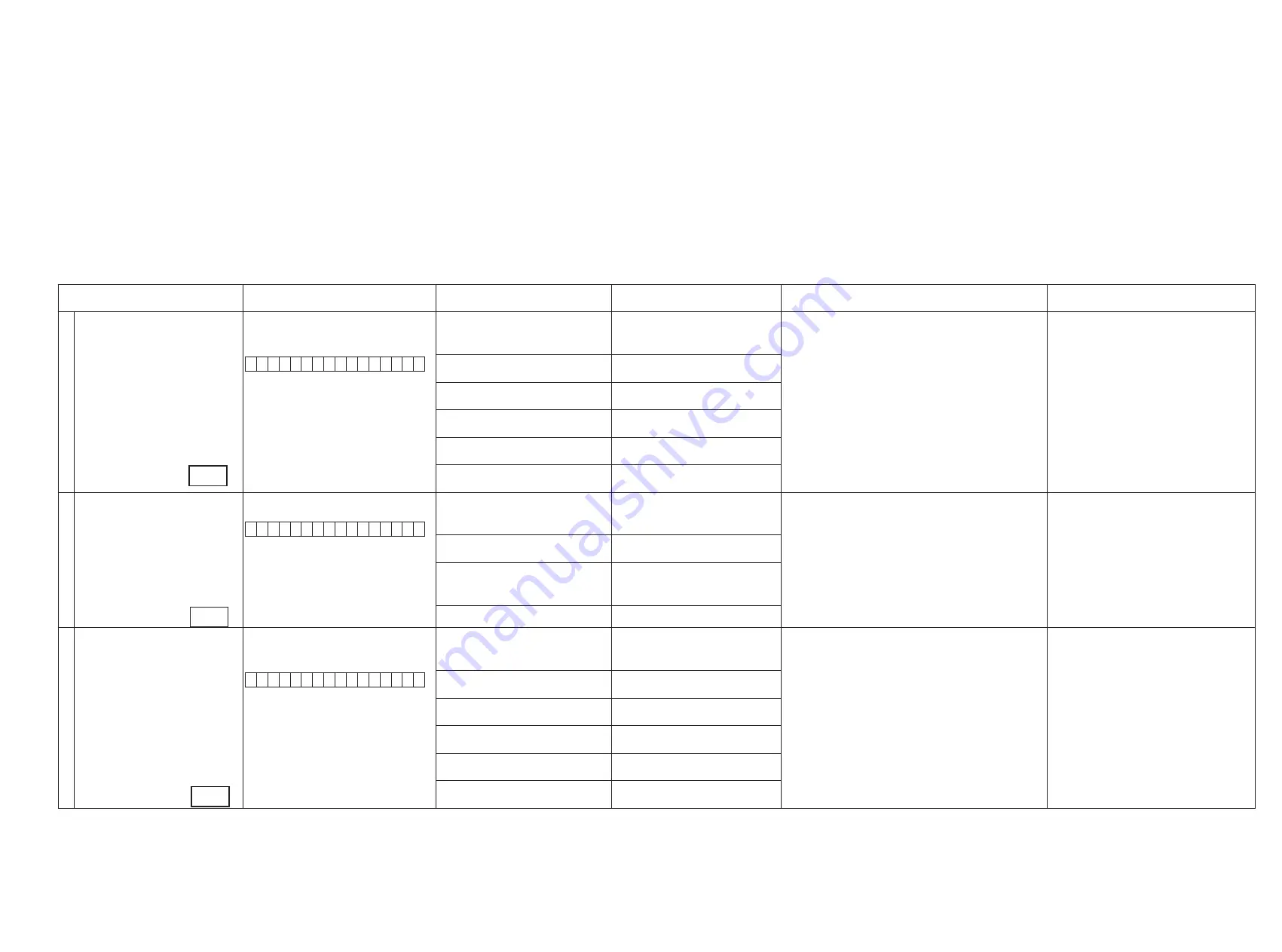
3. DIAGNOSTIC MODE (Video/Audio (signal) path confirmation mode)
d
This mode is used for confirming the Video and Audio (signal) paths. (Troubleshooting)
Confirming the operation of unit can be easily done after repair.
Backup data will not be lost.
3.1. Starting diagnostic mode
Press the "CURSOR LEFT" and "ENTER" botton while simulltaneously pressing those two bottons of this unit.
Q1, Q2 and Q3 are lit in FL display.
3.2. Canceling diagnostic mode
Turn off the power by pressing the ON/Standby botton.
3.3. Operation
When you perform remote operation in accordance with the instructions in "Details of how to operate remote controller" *a) in the table below using the remote control unit (RC-1146).
You will find using another remote control unit with the macro functions very useful. To use the macro functions, program a macro function to output a remote control code in accordance with the steps in *b) in the table below.
3.4. Video system confirmation items
fig.XX : Refer to the block diagram of the fig.XXth.
Confirmation item
Setting and display
Details of how to operate remote controller *a)
Output sequence of remote control codes
※
It is useful to form a macro program. *b)
Contents of confirmation
Remarks
1
Analog Video (signal) Path
Video Convert (IP Scaler) : OFF , All Sources
All ZONE : ON
Display:
V 0 1
D V D
1.Press [AMP]
2.Press [ZONE SELECT] , Select "ZONE2"
3.Press [ZONE OFF]
q
ZONE2 POWER OFF
·Input : CVBS / Output : CVBS
·Input : CVBS / Output : CVBS RECOUT (DVR)
·Input : CVBS / Output : CVBS ZONE2
·Input : Component / Output : Component
·Input : Component / Output Component ZONE
(
※
As the input source, you can switch from DVD to other ones.)
4.Press [ZONE SELECT], Select "ZONE3"
5.Press [ZONE OFF]
w
ZONE3 POWER OFF
6.Press [ZONE SELECT], Select "MAIN"
7.Press [1/./]
e
KEY 1/CODE1 (Main Zone)
Initialization & Video Convert All OFF
8.Press [ZONE SELECT], Select "ZONE2"
9.Press [ZONE ON]
r
ZONE2 POWER ON
10.Press [ZONE SELECT], Select "ZONE3"
11.Press [ZONE ON]
t
ZONE3 POWER ON
12.Press [ZONE SELECT], Select "MAIN"
13.Press [DVD]
y
DVD (Main Zone)
2
Analog Video Convert (signal) Path
Video Convert(IP Scaler) : ON , All Sources
Display:
V 0 2
D V D
1.Press [AMP]
2.Press [ZONE SELECT] , Select "ZONE2"
3.Press [ZONE OFF]
q
ZONE2 POWER OFF
·Input : CVBS / Through : V.Decoder and V.Encoder / Output : CVBS
· Input : CVBS / Through : V.Decoder and V.Encoder / Output :
Component
·Input : Component / Through V.Decoder and V.Encoder / Output : CVBS
· Input : Component / Through V.Decoder and V.Encoder / Output :
Component
(
※
As the input source, you can switch from DVD to other ones.)
Confirm the input pass one by one.
Because it becomes only the input of the highest input
becomes Convert/IP Scaler (signal) Path if it inputs it at
the same time.
(HDMI input > Component input > S-VIDEO input >
CVBS input)
Do not connect anything with HDMI Monito OUT.
Because the Convert pass is used with Analog to HDMI
when connecting it.
4.Press [ZONE SELECT], Select "ZONE3"
5.Press [ZONE OFF]
w
ZONE3 POWER OFF
6.Press [ZONE SELECT], Select "MAIN"
7.Press [2/ABC]
e
KEY 2/ABC (Main Zone)
Initialization & Video Convert All ON & IP
Scaler "Analog & HDMI"
8.Press [DVD]
r
DVD (Main Zone)
3
HDMI (signal) Path
Video Convert(IP Scaler) : OFF, All Sources
All ZONE:ON
Display:
V 0 1
D V D
1.Press [AMP]
2.Press [ZONE SELECT] , Select "ZONE2"
3.Press [ZONE OFF]
q
ZONE2 POWER OFF
·Input : HDMI / Output : HDMI
(
※
As the input source, you can switch from DVD to other ones.)
4.Press [ZONE SELECT], Select "ZONE3"
5.Press [ZONE OFF]
w
ZONE3 POWER OFF
6.Press [ZONE SELECT], Select "MAIN"
7.Press [1/./]
e
KEY1/CODE1 (Main Zone)
Initialization & Video Convert All OFF
8.Press [ZONE SELECT], Select "ZONE2"
9.Press [ZONE ON]
r
ZONE2 POWER ON
10.Press [ZONE SELECT], Select "ZONE3"
11.Press [ZONE ON]
t
ZONE3 POWER ON
12.Press [ZONE SELECT], Select "MAIN"
13.Press [DVD]
y
DVD (Main Zone)
21
fig.1
fig.2
fig.3
Summary of Contents for AirPlay AVR-3311CI
Page 46: ...46 Personal notes Personal notes ...
Page 150: ...Personal notes Personal notes 150 ...
Page 157: ...157 R5F3650KNFB HDMI U5500 ...
Page 164: ...164 IS42S32200E6TL HDMI U1602 IS42S32200E6TL Block diagram ...
Page 173: ...173 AK4424ET HDMI U3800 U3801 AK4424ET Block Diagram ...
Page 174: ...174 AK5358BET HDMI U3802 AK5358BET Pin Function ...
Page 178: ...178 HY27UF081G2A TPCB Block Diagram ...
Page 187: ...187 NJW1194A AUDIO IC3007 IC3011 BLOCK DIAGRAM ...
Page 188: ...188 2 FL DISPLAY FLD 19 ST 03GINK FRONT FL601 PIN CONNECTION GRID ASSIGNMENT ...
Page 189: ...189 ANODE CONNECTION ...
Page 216: ...216 Personal notes ...


