


3. Powering The Display
3.1 - Wall Powered
The DENALI 2.0 Interactive Dealer display can be plugged directly into an
100v-240v outlet, or by using the included battery power wiring adapter,
the display can be powered from a standard motorcycle battery, perfect for
those remote events where power isn
’
t available.
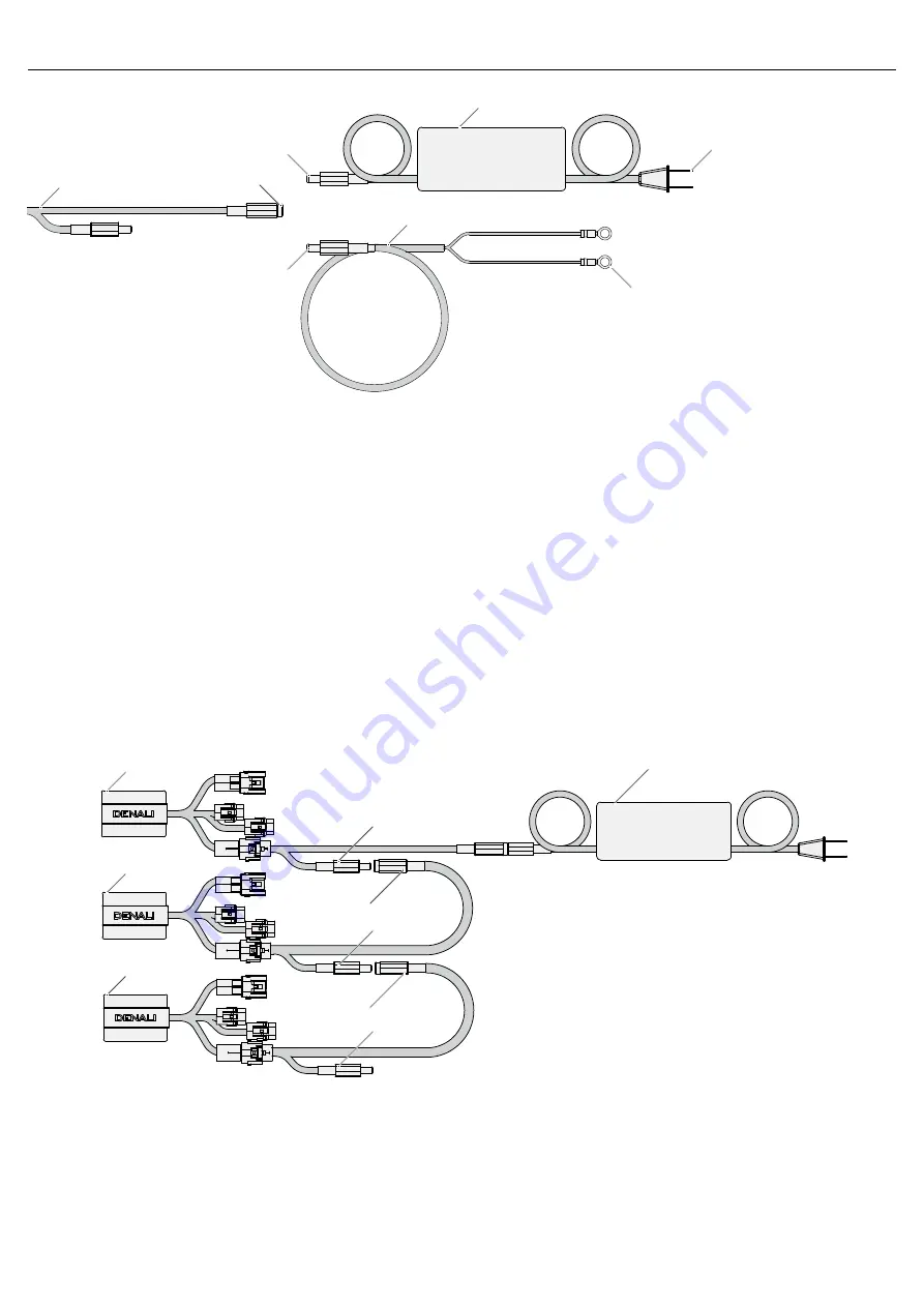
Step One:
Plug the power supply (d) into the display harness (b) “power
input” barrel connector.
Step Two:
Plug the power supply (d) into a standard wall outlet.
Step One:
Plug the battery power adapter (e) into the display harness (b)
“power input” barrel connector.
Step Two:
Connect the battery power adapter (e) to a standard automo-
tive battery via the ring terminals.
3.3 - Daisy Chaining Display Power
If there are multiple displays set up in one location it is possible to power
all the displays from a singular power supply or battery power source.
Step One:
Connect the first display in the series to battery or wall power.
Step Two:
Connect the “Power Output” of the first displays wiring harness
to the “Power Input” of the second displays wiring harness. Continue this
method until all displays have been connected together.
Note:
The power supply has a maximum output of 10 Amps.
3.2 - Battery Powered
Wall Powered
Battery Powered
To 100-240V AC Wall Plug
To 12V DC Battery
12v DC Power (Input)
Display One
Display Two
Display Three
Power Output
Power Input
Power Output
Power Output
Power Input
Origin Power Source
(d)
(e)
(b)


