background image

4. Spare Part List 

H-110-200E                                                       V00 

Page 18 

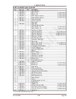
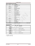
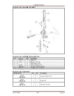
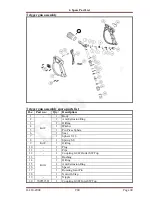
Electrical Box assembly (H-110/200E) 


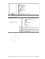
Electrical Box assembly spare-parts list  

Pos: 

Part No: 

Qty: 

Description 


700520586 

Circuit Board Frame 


700590090 

Control Panel 


700530598 

Thermostat Knob 


700590091 

Thermostat Handle Black 


700530267 

Thermostat 


700540777 

Detergent Regulator 


700530599 

Electrical Box 


700590092 

Switch 


10 


11 

700530841 

Thermal Relay 12-18A 

H-110/200E 50/60Hz 

700530256 

Thermal Relay 16-24A 

H-200E 220V 60Hz 

12 

700530842 

Contactor 

H-110E 50/60Hz 

Contactor 

H-200E 400V 50Hz 

Contactor 

H-200E 440V 60Hz 

Contactor 

H-200 220V 60Hz 

13 

700590093 

PLC Circuit Board 


14 

700590094 

LED Electrical Board 


15 

700530736 

Pressure Gauge 


16 

700540776 

Gauge Hose 


18* 

700530765 

Capacitor 65uF 

H-110E 50Hz 

700530848 

Capacitor 90uF 

H-110E 60Hz 

 
* Capacitor not needed for H-200E Machines 

Summary of Contents for H-110-200E

Page 1: ...www densin com USER GUIDE SPARE PARTS MANUAL H 110 200E ELECTRICAL POWERED HEAVY DUTY HOT WATER HIGH PRESSURE CLEANER ...

Page 2: ...tion manual is required in order to prevent injuries to you objects and persons near by Safety The following symbols are used in this manual to indicate procedures that if not followed may results in personal injuries or damage to equipment The information contained in this user guide is subject to change without notice Version 00 May 2015 Revision History Date Revision Rev No WARNING is used to a...

Page 3: ...y H 110 200E 17 Chassis assembly spare parts list 17 Electrical Box assembly H 110 200E 18 Electrical Box assembly spare parts list 18 Boiler assembly H 110 200E 19 Boiler assembly spare parts list 20 Motor assembly H 110E 21 Motor assembly spare parts list 21 Pump assembly H 110E 22 Pump assembly spare parts list 23 Motor assembly H 200E 24 Motor assembly spare parts list 24 Pump assembly H 200E ...

Page 4: ...or Motor Speed Working Pressure Flow Capacity Power Supply Dimension LxWxH Weight Hp kW rpm psi Bar gpm l min Voltage mm kg H 110E 3 0 2 2 1400 1600 110 3 1 11 230 1ph 50Hz 220 1ph 60Hz 940x650x880 110 H 200E 7 5 5 5 1400 2900 200 4 4 15 380 415 3ph 50Hz 220 440 3ph 60Hz 940x650x880 125 Applications These heavy duty high pressure cleaners are capable of removing any kind of dirt The high pressure ...

Page 5: ...he male coupling into the female inlet quick coupling located at bottom rear of the machine Turn on the tap Notice Connection to the public mains water supply according to regulations Put the power plug into a main power supply socket and turn on the power Switch on the high pressure cleaner by depressing the on off switch The high pressure cleaner is now ready for operation The spray gun lance wi...

Page 6: ...laster and its accessories eye protection must be worn to protect against repelling or ricocheting matters causing eye damage 6 Suitable clothing and footwear must be worn while using the equipment to protect the operator Do not try to clean clothes or footwear with the machine 7 Precautions must be made to keep bystanders away from the working range 8 Do NOT spray clean on yourself others or live...

Page 7: ...nob 3 Chemical Suction Control Adjust chemical suction by adjusting the knob 4 Pressure Gauge 5 Boiler switch Start and stop the boiler by depressing this switch Note Chemical can only be dispense at low pressure 6 Fuel Tank Capacity 18L Fill the fuel tank to the left side with automotive quality Diesel Note The Diesel Fuel tank must be filled with diesel in order for the machine to operate as a h...

Page 8: ... Male Outlet Connect to high pressure hose 9 Low Pressure Female Inlet Connect to water supply The machine would operate only as a cold water high pressure cleaner if only the on off switch was depressed By pressing the boiler switch the boiler would be turned on and the machine would function as a hot water cleaner Temperature of the water could be achieved by turning the temperature control knob...

Page 9: ...e machine if important parts are damaged i e safety devices high pressure hoses spray handle 9 The user is obliged to observe all national working environment and working safety regulations concerning operation of high pressure washers 10 It is not allowed to connect this machine directly to a potable water supply 11 If the machine is to be connected to potable water supply it is strictly necessar...

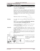
Page 10: ...pe the cabinet Do not use detergent cleaning chemicals Notice To prevent electrical shock DO NOT SPRAY DIRECTLY UPON THE MACHINE WITH HIGH PRESSURE Occasionally clean the fan cover positioned at the back of the motor to ensure sufficient airflow Do NOT operate the machine with damaged or removed fan cover Inspection To prevent electrical shock and spills of leaking water Check electrical cord and ...

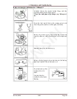
Page 11: ... the fuel nozzle filter with compressed air and check the position and wear of the spark electrodes Remove the boiler cap by unscrewing the 3 nuts and clean the deflector with a brush and or with compressed air Manually take away the interior cap Remove the high pressure hoses and unscrew the locking nuts from beneath Pull out the boiler coil Clean the boiler coil for residue with a wire brush Vac...

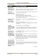
Page 12: ...er supply The pump continuously stops and starts when the spray gun trigger is activated The high pressure nozzle is partly clogged Turn off the high pressure cleaner dismantle the high pressure nozzle and remove the extraneous matter Replace if damaged The high pressure cleaner does not reach the proper working pressure when the spray gun handle is activated The high pressure nozzle is clogged or...

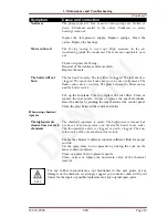
Page 13: ...an or replace the fuel filter Clean or replace the fuel nozzle Adjust or replace the spark electrodes Reset the device by pushing the reset button at the control panel Clean the glass between the censor and boiler When using chemical injector The high pressure cleaner does not suck chemicals The chemical container is empty The high pressure cleaner has not been set to low pressure on the double ba...

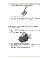
Page 14: ...e poppet up and down to assure that the valve is functioning properly and that no debris is stuck in the valve 5 To reassemble the valves proceed the other way round and tighten the cover screws with a torque wrench Referring to torque specification Servicing the Packing Seals 1 Remove the bolts on the head of the pump 2 Place the screwdrivers between the pump head and crankcase of the pump liftin...

Page 15: ...k 9 To reassemble the packing and seals proceed the other way round and tighten the cover screws with a torque wrench Referring to torque specification Servicing the Plungers Recommend to replace Piston kits Support Rings kits and Water Seals kits whenever servicing the plungers 1 Remove the plunger retainer nut 2 Insert the gasket scraper between the copper washer and plunger to remove the washer...

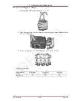
Page 16: ...aft to align the plungers as shown 2 Place the head evenly onto the plungers and push it until it makes contact with the drive end of the pump 3 Torque the head bolts as shown in the tightening sequence diagram Torque Specification Descriptions Pump Head Piston Nut Valve Cap In lbs 133 106 442 Kg m N m 15 12 50 ...

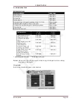
Page 17: ...E 50 60HZ H 200E 50 60HZ Double Barrel Lance 700550457 700550456 Single Barrel Lance 700550450 700550449 Short Double Barrel Lance 700550490 700550488 Single Barrel Lance with Rotating Nozzle 700550470 700550171 Double Barrel Contractor Lance with side Regulator Handle 700550193 700551286 Single Barrel Lance with Multi speed Nozzle 700551289 700550890 Industrial Sandblaster Kit with boron Carbide ...

Page 18: ...4 700590058 1 Left Cover 5 700590057 1 Top Cover 6 700520155 2 Diesel Chemical Tank Cap 7 700540358 2 Gasket 8 700520580 1 Diesel Detergent Tank 9 4 Short Spacer 10 1 Front Wheel Axle 11 1 Back Wheel Axle 12 700590060 4 Wheels w Cover 13 700590059 1 Right Cover 14 700951501 10m Cable 3G2 5 H 110E 50 60Hz 700951502 Cable 4G2 5 H 200E 50 60Hz 15 700520581 1 Back Cover 16 2 Roller Cap 17 4 Long Space...

Page 19: ...ulator 7 700530599 1 Electrical Box 8 9 700590092 1 Switch 10 11 700530841 1 Thermal Relay 12 18A H 110 200E 50 60Hz 700530256 Thermal Relay 16 24A H 200E 220V 60Hz 12 700530842 1 Contactor H 110E 50 60Hz Contactor H 200E 400V 50Hz Contactor H 200E 440V 60Hz Contactor H 200 220V 60Hz 13 700590093 1 PLC Circuit Board 14 700590094 1 LED Electrical Board 15 700530736 1 Pressure Gauge 16 700540776 1 G...

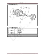
Page 20: ...4 Spare Part List H 110 200E V00 Page 19 Boiler assembly H 110 200E ...

Page 21: ... 50Hz H 110 200E 50Hz 700590009 Blower Motor 60Hz H 200E 60Hz 17 700590010 1 Coupling Fuel Pump Plastic 18 700590040 1 Conic Connection 19 700590097 1 Gas Pump Double Hose 20 2 Washer 21 700590013 1 Nut 1 2 Brass 22 700590098 1 Oil Filter Unit 23 700590050 1 Hose 5 16 L 600mm 24 700590051 1 Hose 3 8 L 375mm 25 700590099 1 Burner Cover 26 1 Band for Burner Cover 27 700590021 1 Chimney for Boiler 28...

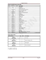
Page 22: ...ssembly H 110E Motor assembly spare parts list Pos Part No Qty Description 1 1 Motor Fan Cover 2 700590061 1 Motor Fan 3 1 Motor Housing 4 700590062 1 Unloading Ring 5 700590063 1 Bearing 6 1 Rotor Shaft 7 700590106 1 Motor Complete 8 1 Motor Flange ...

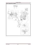
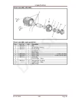
Page 23: ...4 Spare Part List H 110 200E V00 Page 22 Pump assembly H 110E ...

Page 24: ...ng 15 700590078 1 Oil Level Pole 16 700590079 3 Piston Ceramic 15mm 17 700590080 3 Conrod Plug 18 700590081 3 Conrod Complete 19 700590082 1 Oil Indicator 20 700590083 1 O Ring 21 700590084 1 O Ring 22 700590085 3 Oil Seal 23 700590086 1 Pump Shaft 24mm 24 700590087 1 Pump Shaft Key 25 700590088 1 Bearing 26 700590089 1 Seal Ring 27 700590107 1 Pump Head Complete w Unloader 28 700590064 1 Pump Com...

Page 25: ...1 700590109 1 Ring 2 700590110 1 Radial Sphere Bearing 3 700590111 1 Bearing Front 4 1 Cable Holder 5 1 Motor Flange 6 700590108 1 Motor 7 5HP H 200E 380V 50Hz 700590140 Motor 7 5HP H 200E 220 440V 60Hz 7 700590112 1 Feather Key 8 1 Joint 24mm Motor 9 700590113 1 Elastic Rubber Coupling 10 1 Joint 24mm Pump 11 1 Pump Flange ...

Page 26: ...4 Spare Part List H 110 200E V00 Page 25 Pump assembly H 200E ...

Page 27: ...g Flange Front 14 Kit I 1 Water Seal Bushing Kit 15 6 Suction Delivery Plug 16 700590133 6 O Ring 17 1 Holed Valve Cap 1 4 18 Kit J 1 Valve Kit 19 700590135 1 Oil Cap 20 700590136 1 Piston Bushing 21 1 Holed Valve Cap 1 4 22 700590137 1 Pump Head 23 Kit K 1 Piston Screw Kit 24 700590139 1 Bearing Spacer 1 24 700590123 1 Pump Complete H 200E H 200E 50 60Hz Pump repair kits Kit description Pos Qty D...

Page 28: ... Bypass Kit 2 Kit F 1 Pressure Valve Kit 3 1 Body Bypass Valve 4 Kit B 1 Pressure Regulator Kit 5 700590069 1 Greybox with Micro Switch 1 5 700590117 1 Unloader Valve Complete By pass valve repair kits Kit description Pos Qty Description Kit B 700590067 4 1 Pressure Regulator Kit Kit E 700590114 1 1 Bypass Kit Kit F 700590115 2 1 Pressure Valve Kit ...

Page 29: ...ance Pipe Bottom 3 700551470 1 Lance Guard L R Complete w Screws And Holder 4 700551469 1 Nipple Quick Coupling Male 5 700951001 1 Lance Pipe For Double Barrel Lance 6 1 Nozzle Guard complete 7 700550013 2 Bushing High Pressure Nozzle Holder 1 4 8 1 Nozzle Low Pressure 1 8 700551395 1 Lance D B complete w o nozzle 9 700550015 1 Nozzle 15045 1 9 700551473 1 Double Barrel Lance Complete Noz15045 ...

Page 30: ...se w Trigger gun spare part list Pos Part No Qty Description 1 700550003 1 Quick Coupling Female High Pressure 2 700540491 3 O Ring 3 700550004 2 Dowty Seal 3 8 4 700550039 1 High Pressure Hose 3 8 R1T 10m Length 5 700551511 1 Trigger Gun Complete 1 5 700551512 1 Hose HP 10m Quick Coupling Gun 5 ...

Page 31: ... 1 Anti Extrusion Ring 3 1 O Ring 4 1 Washer 5 1 Pin Press Sphere 6 1 Seat 7 1 Sphere 5 16 8 1 Spring S S 9 Kit F 1 O Ring 10 1 Plug 11 1 Pipe 12 1 Coupling G1 4F Outlet SW Top 13 Kit G 1 Bushing 14 1 O Ring 15 1 Anti Extrusion Ring 16 1 Spacer 17 1 Rotating Joint Pin 18 1 Nut with Step 19 1 Nipple 20 700551521 1 Coupling G3 8F Inlet SW Top 30 ...

Page 32: ...700551522 1 Quick Coupling Female Complete 1 30 700551511 1 Trigger Gun Complete Trigger Gun Repair Kits Kit description Pos Qty Description Kit F 700551517 Seat Gasket Repair Kit 2 1 Anti Extrusion Ring 3 1 O Ring 4 1 Washer 5 1 Pin Press Sphere 6 1 Seat 7 1 Sphere 5 16 9 1 O Ring Kit G 700551520 Swivel Repair Kit 13 1 Bushing 14 1 O Ring 15 1 Anti Extrusion Ring 16 1 Spacer 17 1 Rotating Joint P...

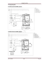
Page 33: ...4 Spare Part List H 110 200E V00 Page 32 Wiring diagrams H 110E 220 230V 50 60Hz Standard H 200E 380 440V 50 60Hz Standard ...

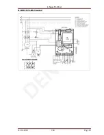
Page 34: ...4 Spare Part List H 110 200E V00 Page 33 H 200E 220V 60Hz Standard ...

Page 35: ...REP KIT X01 VALVE COMPLETE X03 H 110E 50Hz 700550015 700590071 700590072 700590067 700590065 H 110E 60Hz 700550015 700590071 700590072 700590067 700590065 H 200E 50Hz 700550015 700590132 700590114 700590134 H 200E 60Hz 700550015 700590132 700590114 700590134 FOR MACHINE TRIGGER REPAIR KIT X01 INLET STRAINER X02 O RING QUICK COUPLING X04 O RING QUICK COUPLING X02 H 110E 50Hz 700551517 700551520 700...

Page 36: ...ent This warranty does not cover normal wear and tear consumable items or part failures caused by i accident ii abuse or iii failure to maintain the DEN SIN system containing the affected parts in accordance with DEN SIN technical specification All labour is the responsibility and the expense of the Buyer The liability of Seller under this warranty is limited at Seller s option solely to repair or...

Page 37: ...arts Request Form Company Name Delivery Address Country Postal Code Contact Name Contact Number Fax Number Mobile Number Email S N Part Number Description QTY Machine Model or Serial Number 1 2 3 4 5 6 7 8 9 10 11 12 13 14 15 16 17 18 19 20 Special Instructions ...

Page 38: ...This maintenance logbook will assist you to keep track on the servicing of your equipment Please record after service your machine Purchase date of the machine S N Service Description Date Remarks 1 2 3 4 5 6 7 8 9 10 11 12 13 14 15 16 17 18 19 20 21 22 23 24 25 26 27 28 ...

Reviews: