Delta VFD-M-D series User Manual Download Page 115

Chapter 5 Parameters

|

VFD-M-D Series 

5-82


  Revision Jan. 2007, MDE2, SW V1.05
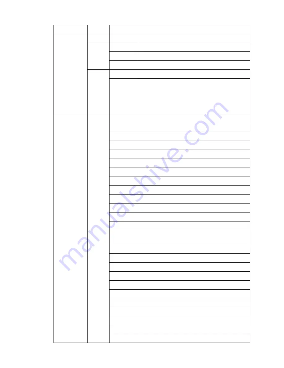
 

Content Address

Function 

2001H

Reserved  

Bit 0 

1: EF (external fault) on  

Bit 1 

1: Reset 

2002H

Bit 2 

Reserved 

Multi-function Input Terminals (COM1~COM4) 

Bit 0 

COM1 

Bit 1 

COM2 

Bit 2 

COM3 


Command 

Write only 

2006H

Bit 3 

COM4 

Error code: 

00: No error occurred 

Status monitor 

Read only 

2100H

01: Over-current (oc) 


02: 

Over-voltage 

(ov) 


03: 

Overheat 

(oH) 


04: 

Overload 

(oL) 


05: 

Overload1 

(oL1) 


06: External fault (EF) 


07: 

Reserved 


08: CPU failure (cF3.3~cF3.8) 


09: Hardware protection failure (HPF.1~HPF.4) 


10: Current exceeds 2 times rated current during accel (ocA)


11: Current exceeds 2 times rated current during decel (ocd)


12: Current exceeds 2 times rated current during steady state 

operation (ocn) 


13: Ground Fault (GFF) 


14: 

Reserved 


15: CPU failure 1 (cF1) 


16: CPU failure 2 (cF2) 


17: 

Reserved 


18: 

Overload 

(oL2) 


19: 

Reserved 


20: Software/password protection (PcdE/Ccde) 


21: 

Reserved 


22: 


Reserved 


23: 


Reserved 

Summary of Contents for VFD-M-D series

Page 1: ...M D...

Page 2: ......

Page 3: ...M D...

Page 4: ...age If you have any questions please contact your dealer PLEASE READ PRIOR TO INSTALLATION FOR SAFETY DANGER 1 AC input power must be disconnected before any wiring to the AC motor drive is made 2 A c...

Page 5: ...your bare hands 3 Only quality person is allowed to install wire and maintain AC motor drive CAUTION 1 Some parameter settings will cause the motor to run immediately after applying power 2 DO NOT in...

Page 6: ...n 1 1 1 1 3 Series Number Explanation 1 2 1 2 Appearances 1 2 1 3 Preparation for Installation and Wiring 1 3 1 3 1 Remove Keypad 1 3 1 3 2 Remove Front Cover 1 3 1 4 Lifting 1 3 1 5 Storage 1 4 Chapt...

Page 7: ...4 2 How to Operate the Digital Keypad LC M2E 4 2 Chapter 5 Parameters 5 1 5 1 Summary of Parameter Settings 5 2 5 2 Description of Parameter Settings 5 15 5 3 The Flow Chart for Parameter Settings 5...

Page 8: ...1 Appendix B Accessories B 1 B 1 All Braking Resistors Braking Units Used in AC Motor Drives B 1 B 1 1 Dimensions and Weights for Braking Resistors B 2 B 2 AMD EMI Filter Cross Reference B 3 B 2 1 Dim...

Page 9: ...C 2 General Precaution C 4 C 3 How to Choose a Suitable Motor C 5...

Page 10: ...ure that the part number indicated on the nameplate corresponds with the part number of your order 1 1 1 Nameplate Information Example for 0 5HP 0 4kW 230V 1 Phase230V AC motor drive Serial Number Bar...

Page 11: ...Production number Production year 2006 Production factory Production week Taoyuan Model 230V 1 phase 0 5HP 0 4kW 0001 If the nameplate information does not correspond to your purchase order or if the...

Page 12: ...ies Revision Jan 2007 MDE2 SW V1 05 1 3 1 3 Preparation for Installation and Wiring 1 3 1 Remove Keypad 1 3 2 Remove Front Cover RST Side UVW Side 1 4 Lifting Please carry only fully assembled AC moto...

Page 13: ...g environment Store within an air pressure range of 86kPA to 106kPA CAUTION 1 DO NOT store in an area with rapid changes in temperature It may cause condensation and frost 2 DO NOT place on the ground...

Page 14: ...type environment CAUTION 1 Operating storing or transporting the AC motor drive outside these conditions may cause damage to the AC motor drive 2 Failure to observe these precautions may void the war...

Page 15: ...abinet they should be adjacent in a row with enough space in between When installing one AC motor drive below another one use a metal separation barrier between the AC motor drives to prevent mutual h...

Page 16: ...Chapter 2 Installation and Wiring VFD M D Series Revision Jan 2007 MDE2 SW V1 05 2 3 2 3 Dimensions Dimensions are in millimeter and inch VFD004M21B D...

Page 17: ...eries are Underwriters Laboratories Inc UL and Canadian Underwriters Laboratories cUL listed and therefore comply with the requirements of the National Electrical Code NEC and the Canadian Electrical...

Page 18: ...DC bus capacitors with hazardous voltages even if the power has been turned off To prevent personal injury please ensure that the power is turned off and wait ten minutes for the capacitors to discha...

Page 19: ...V T2 W T3 IM 3 RS 485 Motor Serial interface 1 2 5 NONE 6 Reserved Reserved Reserved 3 SG 4 SG E RA1 RB1 RC1 Multi function contact output 240VAC 2 5A 120VAC 5A 24VDC 5A output of multi function cont...

Page 20: ...n from AC line disturbances surges switching spikes short interruptions etc AC line reactor should be installed when the power supply capacity is 500kVA or more and exceeds 6 times the inverter capaci...

Page 21: ...actor MC in the power input wiring to cut off power quickly and reduce malfunction when activating the protection function of AC motor drives Both ends of the MC should have an R C surge absorber Do N...

Page 22: ...efer to Appendix B for the use of special braking resistor Connect a brake resistor or brake unit in applications with frequent deceleration ramps short deceleration time too low braking torque or req...

Page 23: ...V direction door open OFF Stop acc to Stop Method MI1 Multi function Input 1 MI2 Multi function Input 2 MI3 Multi function Input 3 MI4 Multi function Input 4 MI5 Multi function Input 5 Refer to Pr 5 0...

Page 24: ...t N C b RC2 Multi function Relay2 common Resistive Load 5A N O 3A N C 240VAC 5A N O 3A N C 24VDC Inductive Load 1 5A N O 0 5A N C 240VAC 1 5A N O 0 5A N C 24VDC Refer to Pr 6 00 and Pr 6 01 for progra...

Page 25: ...ossible from the power wiring and in separate conduits to avoid interference If necessary let them cross only at 90 angle The AC motor drive control wiring should be properly installed and not touch a...

Page 26: ...n Jan 2007 MDE2 SW V1 05 2 13 2 4 5 Main Circuit Terminals 0 5HP 0 4kW VFD004M21B D Control Terminal Torque 2 5Kgf cm 2 2 in lbf Wire 16 22 AWG 1 3 0 3 mm2 Power Terminal Torque 14 kgf cm 12 in lbf Wi...

Page 27: ...Chapter 2 Installation and Wiring VFD M D Series 2 14 Revision Jan 2007 MDE2 SW V1 05 This page intentionally left blank...

Page 28: ...onnected to the AC motor Make sure that all switches are OFF before applying power to ensure that the AC motor drive doesn t start running and there is no abnormal operation after applying power Make...

Page 29: ...1 After applying power verify that the display shows F4 00Hz 2 Pressing RUN key for forward running And if you want to change to reverse running you should press key to display And if you want to dece...

Page 30: ...solving the problem 2 Do NOT touch output terminals U V W when power is still applied to L1 R L2 S L3 T even when the AC motor drive has stopped The DC link capacitors may still be charged to hazardou...

Page 31: ...Chapter 3 Start Up VFD M D Series 3 4 Revision Jan 2007 MDE2 SW V1 05 This page intentionally left blank...

Page 32: ...er or changes the numerical data such as the freq reference Program Function mode key Selects normal mode program mode Displays the AC drive status such as output frequency Enter Key Used to enter pro...

Page 33: ...et the parameters to return to the selection mode NOTE In the parameter setting mode you can press move to previous display parameter set successfully parameter set error Selection mode NOTE In the se...

Page 34: ...fore start up without the need for re adjustment during operation The 9 groups are as follows Group 0 User Parameters Group 1 Basic Parameters Group 2 Motor and Feedback Function Parameters Group 3 Do...

Page 35: ...mmand 00 00 Display output current A 01 Display the pulses 02 Display the walking distance and step speed 1 tt 03 Display DC BUS voltage u 04 Display output voltage E 05 Output power factor angle n 06...

Page 36: ...Open Close Control 02 Disable door close operation 00 00 No limit signal 01 Door open limit signal only 02 Door close limit signal only 03 Door open and close limit signal 0 15 Position Mode 04 Detect...

Page 37: ...Limit 0 00 to 400 0 Hz 0 00 1 12 Skip Frequency 2 Upper Limit 0 00 to 400 0 Hz 0 00 1 13 Skip Frequency 2 Lower Limit 0 00 to 400 0 Hz 0 00 Group 2 Motor and Feedback Function Parameters Parameter Ex...

Page 38: ...00 00 0 00 disable 1 00 2 17 PG Slip Compensation Limit 0 00 to 10 00 Hz 10 00 2 18 Deviation Range of PG Feedback Signal Error 0 01 to 100 Hz 3 00 2 19 PG Feedback Signal Detection Time 0 0 to 100 0...

Page 39: ...g Speed Start 0 0 to 100 0 99 0 3 06 Door Open Holding Speed 0 00 to 400 0Hz 2 00 3 07 Door Open Acceleration Time 1 0 1 to 3600sec 2 0 3 08 Door Open Deceleration Time 1 0 1 to 3600sec 2 0 3 09 Door...

Page 40: ...lose High Speed 2 0 00 to 400 0Hz 20 00 4 08 Door Close Acceleration Time 2 0 1 to 3600sec 10 0 4 09 Door Close Deceleration Time 2 0 1 to 3600sec 10 0 4 10 Re open Current Level 1 0 0 to 150 0 100 0...

Page 41: ...n Input Terminal MI2 03 Multi step speed command 3 00 04 Multi step speed command 4 5 02 Multi Function Input Terminal MI3 05 1st 2nd Accel decel Time Selection 00 5 03 Multi Function Input Terminal M...

Page 42: ...400 0 Hz 0 00 5 18 2nd Step Speed Frequency 0 00 to 400 0 Hz 0 00 5 19 3rd Step Speed Frequency 0 00 to 400 0 Hz 0 00 5 20 4th Step Speed Frequency 0 00 to 400 0 Hz 0 00 5 21 5th Step Speed Frequency...

Page 43: ...ster frequency attained 6 00 Multi function Output RA1 RB1 RC1 03 Over Torque Detection 00 04 Low Voltage Indication 05 Operation Mode Indication 06 Fault Indication 6 01 Multi function Output RA2 RC2...

Page 44: ...eserved Group 7 Protection and Special Parameters Parameter Explanation Settings Factory Setting Customer 7 00 Software Braking Level 370 430 Vdc 380 7 01 DC Braking Current Level 0 0 to 100 0 0 0 7 0...

Page 45: ...ault 00 Speed search starts with the Master Frequency reference value 01 Starts with the minimum output frequency 01 7 14 Auto Reset Time at Restart after Fault 00 to 9999sec 600 00 No fault 01 Over C...

Page 46: ...439 min 00 7 20 Accumulative Motor Operation Day 00 to 9999 day 00 Group 8 Communication Parameters Parameter Explanation Settings Factory Setting Customer 8 00 Communication Address 01 to 254 01 00 B...

Page 47: ...Chapter 5 Parameters VFD M D Series 5 14 Revision Jan 2007 MDE2 SW V1 05 Parameter Explanation Settings Factory Setting Customer 05 8 O 1 Modbus RTU 8 05 Response Delay Time 00 200 msec 00...

Page 48: ...arrier frequency of the AC motor drive correspond to the identity code Pr 0 01 displays the rated current of the AC motor drive By reading this parameter the user can check if the AC motor drive is co...

Page 49: ...ce and step speed x yy y 03 Display the actual DC BUS voltage in VDC of the AC motor drive 04 Display the output voltage in VAC of terminals U V W to the motor 05 Display the power factor angle in of...

Page 50: ...value it displays is hexadecimal number It needs to be converted to binary to get the result as following diagram 2 2 2 2 2 2 2 2 7 6 5 4 3 2 1 0 7 6 5 4 3 2 1 0 0 OFF 1 ON MI1 MI2 MI3 MI4 MI5 FWD RE...

Page 51: ...FF 1 ON The display value bit3x2 bit2x2 bit1x2 bit0x2 1x2 1x2 0x2 0x2 8 4 0 0 12 C H 2 1 0 2 1 0 3 NOTE 2 1 2 8 2 64 2 2 2 16 2 128 2 4 2 32 0 1 2 3 4 5 6 7 Weights Bit 0 05 User Defined Coefficient K...

Page 52: ...ssful input in Pr 0 07 01 Password has been set To set a password to protect your parameter settings If the display shows 00 no password is set or password has been correctly entered in Pr 0 07 All pa...

Page 53: ...r Control Mode Factory Setting 00 Settings 00 Distance control mode 1 01 Distance control mode 2 02 Multi step control mode 1 03 Multi step control mode 2 04 Multi step control mode 3 05 Multi step co...

Page 54: ...4 00 Door Close High Speed 1 4 06 Door Close Deceleration Time 1 4 02 Door Close Final Speed 4 03 Door Close Holding Speed Start Door Close Limit 0 0 4 04 Door Close Holding Speed 01 Distance control...

Page 55: ...to deal with speed switch and limit switch to deal with completed position 4th logic signal open 0 close 1 5 19 3rd step speed 5 27 11th step speed Door Close Limit 0 0 5 17 1st step speed 5 25 9th s...

Page 56: ...tage 00 Distance control mode 1 Uses PG signal to distinguish the position for speed switch without sensor It depends on PG signal highly It will cause pulse loss or wrong position for speed switch wh...

Page 57: ...HP 0 4kW 01 15kHz 12kHz This parameter determines the PWM carrier frequency of the AC motor drive 1kHz 8kHz 15kHz Carrier Frequency Acoustic Noise Electromagnetic Noise or leakage current Heat Dissipa...

Page 58: ...serial communication RJ 11 Keypad STOP enabled 04 RS 485 serial communication RJ 11 Keypad STOP disabled This parameter is used to set the source of the operation command 0 13 Stop Method Factory Sett...

Page 59: ...and free run to stop EF Frequency Frequency frequency output motor speed EF operation command stops according to decel eration time When Pr 0 13 is set to 02 or 03 frequency output free run to stop o...

Page 60: ...ded as open close complete position NOTE It is recommended to use method B for the transmission mechanism skids easily This function is only for the distance control mode For multi step control mode p...

Page 61: ...Chapter 5 Parameters VFD M D Series 5 28 Revision Jan 2007 MDE2 SW V1 05 This parameter determines the control method of the AC motor drive...

Page 62: ...ximum Output Voltage setting must be smaller than or equal to the rated voltage of the motor as indicated on the motor nameplate This parameter value must be equal to or greater than the Mid Point Vol...

Page 63: ...1 07 Frequency Setting for Low Speed Operation Unit 0 1 Settings 0 10 Hz to 400 0 Hz Factory Setting 4 00 1 08 Acceleration Time for Low Speed Operation Unit 0 1 Settings 0 1 to 3600 sec Factory Setti...

Page 64: ...it switch error or input position signal again 1 10 Skip Frequency 1 Upper Limit Unit 0 01 1 11 Skip Frequency 1 Lower Limit Unit 0 01 1 12 Skip Frequency 2 Upper Limit Unit 0 01 1 13 Skip Frequency 2...

Page 65: ...nected to any belt or gear motor 3 Fill in Pr 1 02 Pr 1 01 Pr 2 01 and Pr 2 06 with correct values 4 After Pr 2 00 is set to 2 the AC motor drive will execute auto tuning immediately after receiving a...

Page 66: ...ory Setting 04 This parameter sets the number of motor poles must be an even number 2 05 Motor Line to line Resistance R1 Unit 0 01 Settings 0 00 to 99 99 Factory Setting 0 00 The motor auto tune proc...

Page 67: ...r instable By using this parameter it will improve this situation greatly The drift current zone of the big horsepower motor is usually in the low frequency area It is recommended to set to 07 2 11 PG...

Page 68: ...r Electrical Gear B 2 14 Electrical Gear A 2 13 2 15 ASR Auto Speed Regulation for door open control with PG only P Unit 0 1 Settings 0 0 to 10 0 Factory Setting 0 5 This parameter specifies Proportio...

Page 69: ...s the time during which the PG feedback must be abnormal before a warning see Pr 2 20 is given It also can be modified according to the system feedback signal time If this parameter is set to 0 0 the...

Page 70: ...nger elevator Therefore it needs to have door width auto tuning function to measure the correct door width for the correct position and door open close The procedure for the door width auto tuning fun...

Page 71: ...26 Reserved 2 27 Reserved 2 28 ASR Auto Speed Regulation for door close control with PG only P Unit 0 1 Settings 0 0 to 10 0 Factory Setting 0 5 This parameter specifies Proportional control and asso...

Page 72: ...r Open Holding Speed Start Unit 0 1 Settings 0 0 100 0 0 0 close complete 100 0 open complete Factory Setting 99 0 3 06 Door Open Holding Speed Unit 0 01 Settings 0 00 400 0Hz Factory Setting 2 00 3 0...

Page 73: ...0 100 0 Factory Setting 50 0 3 13 Response Time of Door Open Holding Torque Unit 0 01 Settings 0 01 10 00sec Factory Setting 0 20 When the door is in the open complete position it needs holding torqu...

Page 74: ...setting to close the door When Pr 3 17 is set to 999 9 REV terminal is always holding it needs to stop AC Motor Drive by RESET STOP key on the keypad 3 18 S Curve Acceleration Time for Door Open Unit...

Page 75: ...5 23 5 24 5 25 5 26 5 27 5 28 5 29 1 2 3 4 5 6 7 8 9 10 11 12 13 5 17 REV MI1 MI2 MI3 05 00 1 05 01 2 05 02 3 MI4 05 03 4 5 25 5 25 5 25 FWD 5 30 5 31 5 32 14 15 16 A 05 04 17 Timing Diagram for the...

Page 76: ...2 Pr 0 09 3 MI1 MI2 MI3 05 00 1 05 01 2 05 02 3 MI3 05 03 17 5 19 3rd step speed 5 17 1st step speed 5 18 2nd step speed 5 20 4th step speed 5 21 5th step speed Door Open REV 5 22 6th step speed 5 23...

Page 77: ...9 Multi step mode 3 Pr 0 09 4 FWD REV 5 18 5 19 5 20 5 21 5 22 Door Open REV MI1 MI2 MI3 MI4 05 00 1 05 01 2 05 02 3 05 03 4 MI5 05 04 17 Door Open Limit 3 07 1st Step Door Open Acceleration Time 3 0...

Page 78: ...10 Multi step mode 4 Pr 0 09 5 FWD REV MI1 MI2 MI3 MI4 5 18 5 19 5 20 5 21 5 22 Door Open REV Timing Diagram for the Door Open 05 00 1 05 01 2 05 02 3 05 03 4 MI5 05 04 17 Door Open Limit 3 07 1st St...

Page 79: ...etting 1 0 4 04 Door Close Holding Speed Unit 0 01 Settings 0 00 400 0Hz Factory Setting 2 00 4 05 Door Close Acceleration Time 1 Unit 0 1 Settings 0 1 3600sec Factory Setting 2 0 4 06 Door Close Dece...

Page 80: ...open Current Level 1 Unit 0 1 Settings 0 0 150 0 100 0 is drive rated current Factory Setting 100 0 4 11 Re open Current Level 1 for Acceleration Area Unit 1 Settings 100 200 100 is Pr 4 10 setting Fa...

Page 81: ...celeration area Please refer to following figure for setting re open current and acceleration area 3 02 1st Step Door High Speed Open Open Door REV 3 06 Door Open Holding Speed 3 08 1st Step Door Open...

Page 82: ...e to Pr 4 15 after Door Close Unit 0 1 Settings 0 0 150 0 Factory Setting 50 0 After the door is in the close complete position the door will be in holding torque state when the motor stall exceeds th...

Page 83: ...al acceleration time 4 05 4 23 2 Timing diagram for multi step door close 1 Multi step mode 1 Pr 0 09 2 1 2 3 4 5 6 7 8 9 10 11 12 13 14 15 16 FWD MI1 MI2 MI3 05 00 1 05 01 2 05 02 3 MI4 05 03 4 REV B...

Page 84: ...0 09 3 Door Close FWD FWD REV MI1 MI2 MI3 05 00 1 05 01 2 05 02 3 MI5 05 04 18 Door Close Limit 5 27 11th step speed 5 25 9th step speed 5 26 10th step speed 5 30 14th step speed 5 29 13th step speed...

Page 85: ...V1 05 3 Multi step mode 3 Pr 0 09 4 FWD REV 5 23 5 24 5 27 5 26 5 25 Door Close FWD MI1 MI2 MI3 MI4 05 00 1 05 01 2 05 02 3 05 03 4 A 05 05 18 Door Close Limit 4 06 Door Close Deceleration Time 1 4 0...

Page 86: ...5 5 53 4 Multi step mode 4 Pr 0 09 5 FWD REV 5 23 5 24 5 27 5 26 5 25 Door Close FWD MI1 MI2 MI3 MI4 05 00 1 05 01 2 05 02 3 05 03 4 05 05 18 A Door Close Limit 4 06 Door Close Deceleration Time 1 4 0...

Page 87: ...t Terminal A Factory Setting 00 5 06 Multi function Input Terminal B Factory Setting 00 5 07 Multi function Input Terminal COM1 Factory Setting 00 5 08 Multi function Input Terminal COM2 Factory Setti...

Page 88: ...mmand for Low Speed Operation ON REV OFF FWD This command will be effective only when external terminal for low speed operation is active 08 Demo Mode When this setting is enabled the output frequency...

Page 89: ...ction 22 The curve selection for 1st 2nd step door open close When this setting is ON it will run the curve of 2nd step door open close 23 The signal when it is in open completed position including RU...

Page 90: ...eration Control Modes Factory Setting 00 Settings 00 2 wire FWD STOP REV STOP 01 2 wire FWD REV RUN STOP There are two different types of control modes 5 12 External Terminal 00 2 wire FWD STOP REV ST...

Page 91: ...Frequency Unit 0 01 5 21 5th Step Speed Frequency Unit 0 01 5 22 6th Step Speed Frequency Unit 0 01 5 23 7th Step Speed Frequency Unit 0 01 5 24 8th Step Speed Frequency Unit 0 01 5 25 9th Step Speed...

Page 92: ...alue to decimal value before entering this parameter For example Suppose that the initial status of REV MI2 MI4 MI5 COM1 COM2 and COM4 is N C The initial status of FWD MI1 MI3 A B and COM3 is N O At t...

Page 93: ...pad LC M2E will display PSEr position signal error when following item occurs 1 When Pr 5 34 is set to Bit0 1 and Pr 0 09 is set to 00 or 01 incorrect door open close limit 2 When Pr 5 34 is set to Bi...

Page 94: ...it isn t received after Pr 4 03 setting Incorrect door close limit a The signal for the door open limit is received before Pr 3 03 setting b The signal for the door open limit isn t received after Pr...

Page 95: ...Factory Setting 00 6 06 Multi function Output Terminal MO5 communication Factory Setting 00 6 07 Multi function Output Terminal MO6 communication Factory Setting 00 Settings 00 to 26 These parameters...

Page 96: ...ts it will signal to prevent OH turn off the drive When it is higher than 85o C 185o F it will be ON Or it will be OFF 13 AC Motor Drive Ready Active when the drive is ON and no abnormality detected o...

Page 97: ...n Active when position mode Pr 0 15 is set to 01 or 03 and one of the Pr 5 00 to Pr 5 10 is set to 17 23 Door Close Error Active when door close error no matter it will re open or not 24 Reserved 25 P...

Page 98: ...N C MO5 N C MO6 N O 0 N O 1 N C 6 5 4 3 2 1 0 6 5 4 3 2 1 0 NOTE 2 1 2 8 2 64 2 2 2 16 2 128 2 4 2 32 0 1 2 3 4 5 6 7 When Pr 6 00 to Pr 6 07 is set to 18 to 20 it will output a signal once the door i...

Page 99: ...me during Start up Unit 0 1 Settings 0 0 to 999 9 sec Factory Setting 0 0 This parameter determines the duration of the DC Braking current after a RUN command When the time has elapsed the AC motor dr...

Page 100: ...detected keep running until oL2 occurs 02 Over Torque detection enabled during constant speed operation After over torque is detected stop running 03 Over Torque detection enabled during acceleration...

Page 101: ...2 Operation disabled This function is used to protect the motor from overloading or overheating 40 20 60 80 100 25 50 100 150 Motor rated freqency Motor rated current Self cooled by fan 25 50 100 150...

Page 102: ...ttings 0 1 to 600 0 sec Factory Setting 2 0 This parameter should be set at a value to ensure that any residual regeneration voltage from the motor on the output has disappeared before the drive is ac...

Page 103: ...nit 1 Settings 00 to 9999 sec Factory Setting 600 7 15 Present Fault Record 7 16 Second Most Recent Fault Record 7 17 Third Most Recent Fault Record 7 18 Fourth Recent Fault Record Factory Setting 00...

Page 104: ...35 Communication time out CE10 In Pr 7 15 to Pr 7 18 the four most recent faults that occurred are stored After removing the cause of the fault use the reset command to reset the drive 7 19 Accumulati...

Page 105: ...s 01 to 254 Factory Setting 01 If the AC motor drive is controlled by RS 485 serial communication the communication address for this drive must be set via this parameter And the communication address...

Page 106: ...TU mode protocol 8 O 1 1 Control by PC or PLC A VFD M D can be set up to communicate on Modbus networks using one of the following modes ASCII American Standard Code for Information Interchange or RTU...

Page 107: ...it 0 1 2 3 4 5 6 Even parity Stop bit 11 bit character frame 8 E 1 Start bit 0 1 2 3 4 5 6 Stop bit 11 bit character frame 8 O 1 Odd parity 7 7 7 8 bit character 8 bit character 3 Communication Protoc...

Page 108: ...AC drives AMD In this case the AMD will not reply any message to the master device 00H broadcast to all AC drives 01H AC drive of address 01 0FH AC drive of address 15 10H AC drive of address 16 FEH A...

Page 109: ...and message Response message Address 01H Address 01H Function 03H Function 03H 21H Starting data address 02H Number of data count by byte 04H 00H 17H Number of data count by word 02H Content of addres...

Page 110: ...to know if the communication between master device PC or PLC and drive is normal The drive will send back the received data to master device ASCII Mode Command message Response message STX STX Address...

Page 111: ...ing data address 0 0 0 0 0 0 0 Number of data count by word 2 Number of data count by word 2 0 E Number of data count by byte 4 LRC Check 8 1 CR 3 END LF 8 The first data content 8 0 F A The second da...

Page 112: ...Function 0 3 0 4 0 Starting data address 1 0 0 0 Number of data 1 F LRC Check 1 LRC Check 0 6 CR END 1 END 0 LF 01H 03H 04H 01H 00H 01H 0AH the 2 s complement negation of 0AH is F6H RTU mode Address...

Page 113: ...ytes have been processed The final contents of the CRC register are the CRC value When transmitting the CRC value in the message the upper and lower bytes of the CRC value must be swapped i e the lowe...

Page 114: ...r Open Accel Decel 01B 1st Step Door Close Accel Decel 10B 2nd Step Door Open Accel Decel 11B 2nd Step Door Close Accel Decel 0000B 1st Step Speed Frequency 0001B 2nd Step Speed Frequency 0010B 3rd St...

Page 115: ...rrent oc 02 Over voltage ov 03 Overheat oH 04 Overload oL 05 Overload1 oL1 06 External fault EF 07 Reserved 08 CPU failure cF3 3 cF3 8 09 Hardware protection failure HPF 1 HPF 4 10 Current exceeds 2 t...

Page 116: ...munication interface Bit 11 1 Parameters have been locked Bit 12 0 AC drive stops 1 AC drive operates Bit 13 1 Jog command Status monitor Read only 2101H Bit 14 15 Reserved 2102H Frequency command F 2...

Page 117: ...arameter copy check failure SE2 18 overload oL2 26 PG feedback error PGEr 27 limit signal error PSEr 31 illegal function code cE01 32 illegal data address cE02 33 illegal data value cE03 34 slave devi...

Page 118: ...C3H Function Low Function High 6 CRC CHK High A1H 0 Exception code 2 7 LRC CHK Low LRC CHK High 7 CR END 1 END 0 LF The explanation of exception codes Exception code Explanation 01 Illegal function co...

Page 119: ...th address 1 unsigned char tdat 60 0 1 0 3 2 1 0 2 0 0 0 2 D 7 r n void main int i outportb PORT MCR 0x08 interrupt enable outportb PORT IER 0x01 interrupt as data in outportb PORT LCR inportb PORT LC...

Page 120: ...e Open Speeds setting Open 3 00 3 06 Close 4 00 4 04 Door OpenAccel Decel Time Setting 3 07 3 08 Door Close Accel Decel Time Setting 4 05 4 06 Door Open Holding Torque Door Close Holding Torque 3 12 3...

Page 121: ...Chapter 5 Parameters VFD M D Series 5 88 Revision Jan 2007 MDE2 SW V1 05 This page intentionally left blank...

Page 122: ...2 Check the wiring connections to U V W for possible short circuits 3 Check the wiring connections between the AC motor drive and motor for possible short circuits also to ground 4 Check for loose co...

Page 123: ...load in motor 3 Check for correct wiring of input power to R S T for 3 phase models without phase loss Overload The AC motor drive detects excessive drive output current NOTE The AC motor drive can wi...

Page 124: ...ation 1 Short circuit at motor output Check for possible poor insulation at the output line 2 Sudden increase in motor loading Check for possible motor stall 3 AC motor drive output power is too small...

Page 125: ...will be locked Turn the power ON after power OFF to re enter the correct password See Pr 0 07 and 0 08 PG feedback signal error 1 Check parameter settings and signal type of PG feedback Pr 2 11 to Pr...

Page 126: ...ompensation Reduce torque compensation Suitable torque compensation No No No No No Yes Yes Yes Yes Yes Maybe AC motor drive has malfunction or error due to noise Please contact with DELTA Can accelera...

Page 127: ...ltage to be within spec Has over voltage occurred without load Maybe AC motor drive has malfunction or misoperation due to noise Please contact with DELTA Yes Yes Yes Yes Yes Yes No No No No No When O...

Page 128: ...specification Make necessary corrections such as change power supply system for requirement Check if there is heavy load with high start current in the same power system Check if Lv occurs when break...

Page 129: ...ormally Change cooling fan Check if cooling fan is jammed Remove obstruction Check if surrounding temperature is within specification Adjust surrounding temperature to specification Maybe AC motor dri...

Page 130: ...all connectors are connect correctly and no noise is present AC motor drive has malfunction Please contact DELTA 7 8 Phase Loss PHL Phase loss No No Yes Yes Check wiring at R S and T terminals Correct...

Page 131: ...ase contact DELTA Press UP key to set frequency Yes Modify frequency setting Check if input FWD or REV command Check if the wiring of terminal FWD and between REV DCM is correct Yes Change switch or r...

Page 132: ...Yes If finished with executing Pr 05 15 If the setting of Pr 05 00 to Pr 05 14 are the same Is it in PLC mode Press UP DOWN key to see if speed has any change If there is any change of the signal that...

Page 133: ...ease contact DELTA Increase torque compensation Check if the torque compensation is suitable Thicken or shorten the wiring between the motor or AC motor drive Reduce load or increase the capacity of A...

Page 134: ...ceive 7 14 Environmental Condition Since the AC motor drive is an electronic device you should comply with the environmental condition stated in the Chapter 2 1 Following are the remedial measures for...

Page 135: ...cuit 3 If phase lead capacitors are used never on the AC motor drive output use serial reactors to prevent capacitors damage from high harmonics serial reactor phase lead capacitor Motor Temperature R...

Page 136: ...4 Whether any irregular vibration or sound occurred during operation 5 Whether the motors are overheating during operation 6 Always check the input voltage of the AC drive with a Voltmeter Periodic In...

Page 137: ...cts Visual inspection Voltage Maintenance Period Check Items Methods and Criterion Daily Half Year One Year Check if the voltage of main circuit and control circuit is correct Measure with multimeter...

Page 138: ...ar One Year If there are any loose or missing screws Tighten or replace the screw If machine or insulator is deformed cracked damaged or with color change due to overheating or ageing Visual inspectio...

Page 139: ...e is any peculiar smell or insulator cracks due to overheat Visual inspection smell If there is any disconnection Visual inspection or measure with multimeter after removing wiring between P N Resisto...

Page 140: ...tion If there is any liquid is leaked or deformation in capacity Visual inspection Cooling fan of cooling system Maintenance Period Check Items Methods and Criterion Daily Half Year One Year If there...

Page 141: ...Chapter 8 Maintenance and Inspections VFD M D Series 8 6 Revision Jan 2007 MDE2 SW V1 05 This page intentionally left blank...

Page 142: ...oled Weight kg 2 2 Control System SPWM Sinusoidal Pulse Width Modulation control V f or sensorless vector control Frequency Setting Resolution 0 01Hz Output Frequency Resolution 0 01Hz Torque Characte...

Page 143: ...ons 1 Form C contact or 1 Form A contact or 2 open collector outputs Operation Functions AVR fault records reverse inhibition DC braking auto torque slip compensation auto tuning adjustable carrier fr...

Page 144: ...e Watt and the duty cycle value ED 2 If damage to the drive or other equipment are due to the fact that the braking resistors and the braking modules in use are not provided by Delta the warranty will...

Page 145: ...B Accessories VFD M D Series B 2 Revision Jan 2007 MDE2 SW V1 05 B 1 1 Dimensions and Weights for Braking Resistors Dimensions are in millimeter TYPE L1 L2 H D W MAX WEIGHT g BR080W200 140 125 20 5 3...

Page 146: ...1st Environment restricted distribution General precaution 1 EMI filter and AC motor drive should be installed on the same metal plate 2 Please install AC motor drive on footprint EMI filter or instal...

Page 147: ...motor terminals will experience surge voltages easily due to components conversion of AC motor drive and cable capacitance When the motor cable is very long especially for the 460V series surge voltag...

Page 148: ...0m or less To prevent it please use AC reactor and or lower the carrier frequency Pr 02 03 PWM carrier frequency NOTE Never connect phase lead capacitors or surge absorbers to the output terminals of...

Page 149: ...sories VFD M D Series B 6 Revision Jan 2007 MDE2 SW V1 05 B 2 1 Dimensions Dimensions are in millimeter and inch Order P N RF015M21AA 70 2 76 226 8 9 100 3 94 212 8 35 212 8 35 28 1 1 50 1 97 26 1 02...

Page 150: ...ue 230V 50 60Hz 3 Phase Inductance mH kW HP Fundamental Amps Max continuous Amps 3 impedance 5 impedance 0 4 0 5 4 6 6 5 9 B 3 3 Applications for AC Reactor Connected in input circuit Application 1 Qu...

Page 151: ...drive AC motor drive motor motor motor Application 2 Question Silicon rectifier and AC motor drive is connected to the same power Surges will be generated at the instant of silicon rectifier switchin...

Page 152: ...ort interruptions etc AC line reactor should be installed when the power supply capacity is 500kVA or more and exceeds 6 times the inverter capacity or the mains wiring distance 10m When power capacit...

Page 153: ...0A Dimensions are in millimeter and inch Motor HP kW Qty Recommended Wire Size mm2 Wiring Method 230V Series 1 2 0 5 1 0 5 5 5 Please wind each wire 4 times around the core The reactor must be put at...

Page 154: ...the current rating of the breaker shall be 4 times maximum input current rating Refer to Appendix A for rated input output current 1 phase Model Recommended non fuse breaker A VFD004M21B D 6 3 B 6 Fus...

Page 155: ...Appendix B Accessories VFD M D Series B 12 Revision 10 2005 BE13 This page intentionally left blank...

Page 156: ...peed power and the change of load capacity The following table lists the factors you need to consider depending on your requirements Related Specification Item Speed and torque characteristics Time ra...

Page 157: ...than the rated capacity of AC motor drive Acceleration time 60 seconds The starting capacity _ _ _ _ _ 5 1 1 cos 1 1 1 kVA drive motor AC of capacity the k n n P k n n N k s C s s T s T Acceleration t...

Page 158: ...t of AC motor drive A _ _ _ _ _ _ A drive motor AC of current rated the I k M Symbol explanation M P Motor shaft output for load kW Motor efficiency normally approx 0 85 cos Motor power factor normall...

Page 159: ...e motor D O L Direct On Line a lower starting torque output with AC Motor Drive can be expected If higher starting torque is required such as for elevators mixers tooling machines etc use an AC Motor...

Page 160: ...apacity for both the motor and the AC Motor Drive C 3 How to Choose a Suitable Motor Standard motor When using the AC Motor Drive to operate a standard 3 phase induction motor take the following preca...

Page 161: ...s required for operation at 50 or 60 Hz and higher frequency To avoid resonances use the Skip frequencies 9 The motor fan will be very noisy when the motor speed exceeds 50 or 60Hz Special motors 1 Po...

Page 162: ...motors Please check before operation and choose the capacity of the AC motor drive carefully When the AC motor drive operates more than one motor please pay attention to starting and changing the mot...

Page 163: ...econds Base freq 60Hz V F for 220V 60Hz 180 155 100 55 38 0320 60 120 torque Frequency Hz Frequency Hz 60 seconds 60 seconds torque Base freq 60Hz V F for 220V 60Hz 130 140 100 85 45 35 0320 50 120 18...

Reviews: