background image


Step 8: Test Feedback Device 

deltamotion.com 


19 

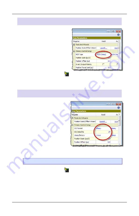
Start/Stop or PWM (Magnetostrictive)  Feedback 

1.


In the 

Axis Parameters

, on 

the 

Setup

 tab, set the 

MDT 

Type

 register to the type of 

magnetostrictive transducer 
you have. 
This information is available 
from your transducer 
datasheet. 

2.


Click the 

Download

 button 

 to apply the changes to the RMC. 

3.


Continue to the 

Verify Feedback

 section on page 21. 

SSI Feedback 

1.


In the 

Axis Parameters

 pane, 

on the 

Setup

 tab, set the 

following cells. 


SSI Format 


SSI Data bits

 (e.g. 24)


Linear/Rotary 
 

This information is available 
from your SSI device data 
sheet.


Note: 

For help on a parameter, click the cell and press F1. 

2.


Click the 

Download

 button 

 to apply the changes to the RMC. 

3.


Continue to the 

Verify Feedback

 section on page 21. 


Summary of Contents for RMC150

Page 1: ...RMC150 MOTION CONTROLLER STARTUP GUIDE With wiring diagrams Motion Control and More...

Page 2: ...e to Get Help Video Tutorials In RMCTools on the Help menu click Video Tutorials RMCTools Help In RMCTools on the Help menu click Help Topics Forum forum deltamotion com Delta Technical Support Phone...

Page 3: ...e the Axes 12 Step 7 Test an Actuator 14 Step 8 Test Feedback Device 18 Step 9 Scale and Offset 22 Step 10 Set the Output Polarity 23 Step 11 Tuning 24 Continuing the Motion Application 27 Diagnostic...

Page 4: ...ons Symmetrical DIN 3 Panel mount See Discrete Input Wiring To turn on a discrete input apply a voltage of the correct level The polarity is unimportant DI O and UI O Module Because all the inputs sha...

Page 5: ...Step 1 Mounting deltamotion com 3 RMC150E Module Each input has a and connection Example...

Page 6: ...d below depends on the maximum ambient temperature Ambient Temperature Clearance 122 140 F 50 60 C 3 in 7 6 cm 86 122 F 30 50 C 2 in 5 1 cm Less than 86 F 30 C 1 in 2 5 cm Grounding Make sure to prope...

Page 7: ...30 Note Remove power from the RMC before connecting any wires Wiring Topic Page General Wiring Information 31 Power 32 Control Output Drive 32 SSI Inputs 33 Start Stop and PWM Inputs Magnetostrictive...

Page 8: ...150 category then choose the Software category 3 Choose the RMCTools 32 bit or 64 bit version as required for your computer 4 Run the rmctoolsinstall32 exe or rmctoolsinstall64 exe file and follow the...

Page 9: ...to the PC and to the RMC150E USB port This type of USB cable is used for PC peripherals such as printers and is available at any store that sells electronics Or use Ethernet Cable Connect an Ethernet...

Page 10: ...ep 5 Start a New Project 1 Start RMCTools 2 In the Startup dialog choose Create a New Project and click OK 3 Enter the Project Name then click Finish 4 In the New Controller Wizard choose Automaticall...

Page 11: ...t and click Next RMC150E via Ethernet A Click Ethernet and click Next B Use the MAC address on the RMC150E label to identify the RMC in the list then click the RMC C If the RMC does not have an IP add...

Page 12: ...o the RMC and display it Verify it is correct then click Finish 7 The toolbar now displays This means RMCTools is communicating with the controller Project Pane The project pane contains all the items...

Page 13: ...be Quadrature Input or SSI Axis Input For more details refer to the UI O module topic in the RMCTools help Saving Settings Throughout the startup procedure make sure to save the configuration changes...

Page 14: ...tart of the project Major changes to axes later may result in lost axis parameters Example Axis Definitions Position Control Axis One Control Output one position input Position Force Control Axis all...

Page 15: ...gned hardware click an axis in the list The hardware assigned to that axis will be highlighted in the image Edit Axis Definitions Use the Axis Definitions dialog to change the axis definitions Click N...

Page 16: ...already have been wired to the RMC USE THE DIRECT OUTPUT COMMAND WITH CAUTION IT DISABLES THE SAFETY FEATURES OF THE RMC Fault Controller Button If the motion causes problems be prepared to quickly s...

Page 17: ...Step 7 Test an Actuator deltamotion com 15 3 In the Axis Status Registers on the Basic tab look at the Control Output It should be 0...

Page 18: ...to click the button 6 Browse to Motion Commands then Open Loop Choose the Direct Output command and click OK 7 For the Direct Output command parameters enter the following Output 0 1 Ramp Rate 100 Wh...

Page 19: ...ut for enabling the actuator such as a motor drive then you first need to set the Enable Output before trying to move the actuator For details see the Set Enable Output 67 Command topic in the RMCTool...

Page 20: ...the Axis Parameters pane on the Setup tab you will configure certain parameters depending on the type of input you are using Refer to the procedure for your transducer type and module Transducer Type...

Page 21: ...Click the Download button to apply the changes to the RMC 3 Continue to the Verify Feedback section on page 21 SSI Feedback 1 In the Axis Parameters pane on the Setup tab set the following cells SSI...

Page 22: ...lick the Download button to apply the changes to the RMC 3 Continue to the Verify Feedback section on page 21 Quadrature Encoder Feedback The QUAD module does not require any configuration Continue to...

Page 23: ...Counts Volts or Current register It may be changing slightly 3 Use the Direct Output command to move the axis back and forth as described in the Test an Actuator section 4 As the axis moves look for...

Page 24: ...rds section 2 Click Launch in the desired axis 3 In the wizard follow the directions For help press the Help button Tip If the wizard does not work for your system you can manually determine the Scale...

Page 25: ...al Position and note whether it is increasing or decreasing Increasing The Output Polarity is correct Go to Enable the Axes below Decreasing You must invert the Output Polarity A In the Axis Parameter...

Page 26: ...ools 2 Set Up Tuning Tools Set up the buttons that you will use to move the axis back and forth after autotuning is complete Click the first button labeled Click to set up Enter a Move Absolute comman...

Page 27: ...not following the Target Position very well pull the slider bar up apply gains and move the axis again Repeat until the Actual Position tracks the Target Position very well Tuning With an Existing Pl...

Page 28: ...menu choose Help Topics 5 On the Index tab type tuning and double click about 6 The Tuning Overview topic describes tuning In the Manual Tuning section choose a procedure For most position control ap...

Page 29: ...imple or advanced sequences of commands on the RMC This allows the RMC to respond to events within its control loop time rather than the scan rate of a PLC or other host controller It also reduces the...

Page 30: ...in the RMCTools help for details Variables Variables help make the User Programs very flexible and easy to maintain Variables can be used to effortlessly change programs and easily modify User Progra...

Page 31: ...Event Log Monitor displays all events that have occurred in the controller such as issued commands changed parameters and errors The Event Log Monitor is an important aid in troubleshooting The Event...

Page 32: ...ult the RMCTools help Note Remove power from the RMC before connecting any wires Wiring Topic Page General Wiring Information 31 Power 32 Control Output Drive 32 SSI Inputs 33 Start Stop and PWM Input...

Page 33: ...nd proportional valves For UL and CUL compliance Power supply must be Class 2 All RMC inputs and outputs must be connected to Class 2 circuits only For products labeled Class I Division 2 Conductors m...

Page 34: ...g Backplane Slots 3 4 5 6 Max Current mA 375 500 625 750 UL and CUL Requirements For UL and C UL compliance the power supply must be Class 2 Class 2 power supplies are limited to 100W output No additi...

Page 35: ...ock Data Data Power Supply Pwr Pwr DC Gnd Tip See next page for manufacturer specific wiring diagrams Universal I O Module The Universal I O SSI input wiring is identical to the diagram shown above wi...

Page 36: ...ng instructions on page 33 Balluff Micropulse BTL 5 with SSI output Styles Z W K P Input Connector Clk Clk Data Data Pwr Cmn Clk Clk Cmn Dat Dat Case 24 V GND Yellow Pink Gray Green Brown Blue MTS Tem...

Page 37: ...y Pwr Cmn Int Int Cmn Ret Ret Case Pwr DC Ground Tip See next page for manufacturer specific wiring diagrams Notes The MDT module interfaces to 5V differential RS 422 signals Single ended TTL signals...

Page 38: ...iring instructions on page 35 Balluff Micropulse BTL 5 digital RS 485 output Styles Z W K E P R AT MTS Temposonics with digital output Start Stop or PWM Models LH LS LD LF LPS LPR G EP2 ER MTS Temposo...

Page 39: ...Transducer Wiring Voltage Transducer 4 or 5 Wire Voltage Transducer 3 Wire To reduce electrical interference In and Cmn must be connected either internal to the transducer or externally as close as po...

Page 40: ...asurement accuracy of the potentiometer Not available on the UI O module Analog 4 20 mA Note The Analog G module does not support 4 20 mA To reduce electrical interference The connection of Analog In...

Page 41: ...gle ended TTL are strongly discouraged If absolutely necessary see the RMCTools help for single ended wiring Reg Lim and Home Inputs Compatible with 5 24 VDC They draw 3 5 mA min 10 mA max Universal I...

Page 42: ...input is only used for reference signals outside of these specifications and requires contacting Delta for assistance 8 pin Resolver Connector Ref Winding Ref Winding Sin Winding Cos Winding R1 Ref I...

Page 43: ...SR may occur See the RMC150E Discrete I O Wiring topic in the RMCTools help for more details DI O and UI O Module Outputs can be wired in either a high side or low side configuration Because all the o...

Page 44: ...Computer Systems Inc Each output has a and connection Outputs can be wired in either a high side or low side configuration RMC Module Resistive load VCC 12 24 VDC Output Output RMC Module VCC 12 24 VD...

Page 45: ...mportant DI O and UI O Module Because all the inputs share a common all inputs on the same module must be wired the same Example RMC150E Module Each input has a and connection Example RMC150E DI O UI...

Page 46: ...Delta Computer Systems Inc Appendix B Mounting Dimensions Backplane Slots 3 4 5 6 Total Width 4 10 in 104 1 mm 5 10 in 129 5 mm 6 10 in 154 9 mm 7 10 in 180 3 mm Note Allow space for the connectors o...

Page 47: ...locations and nonhazardous locations only WARNING EXPLOSION HAZARD DO NOT DISCONNECT EQUIPMENT WHILE THE CIRCUIT IS LIVE OR UNLESS THE AREA IS KNOWN TO BE FREE OF IGNITABLE CONCENTRATIONS WARNING EXP...

Page 48: ...The RMC Family of Motion Control Connect Control Optimize...

Reviews: