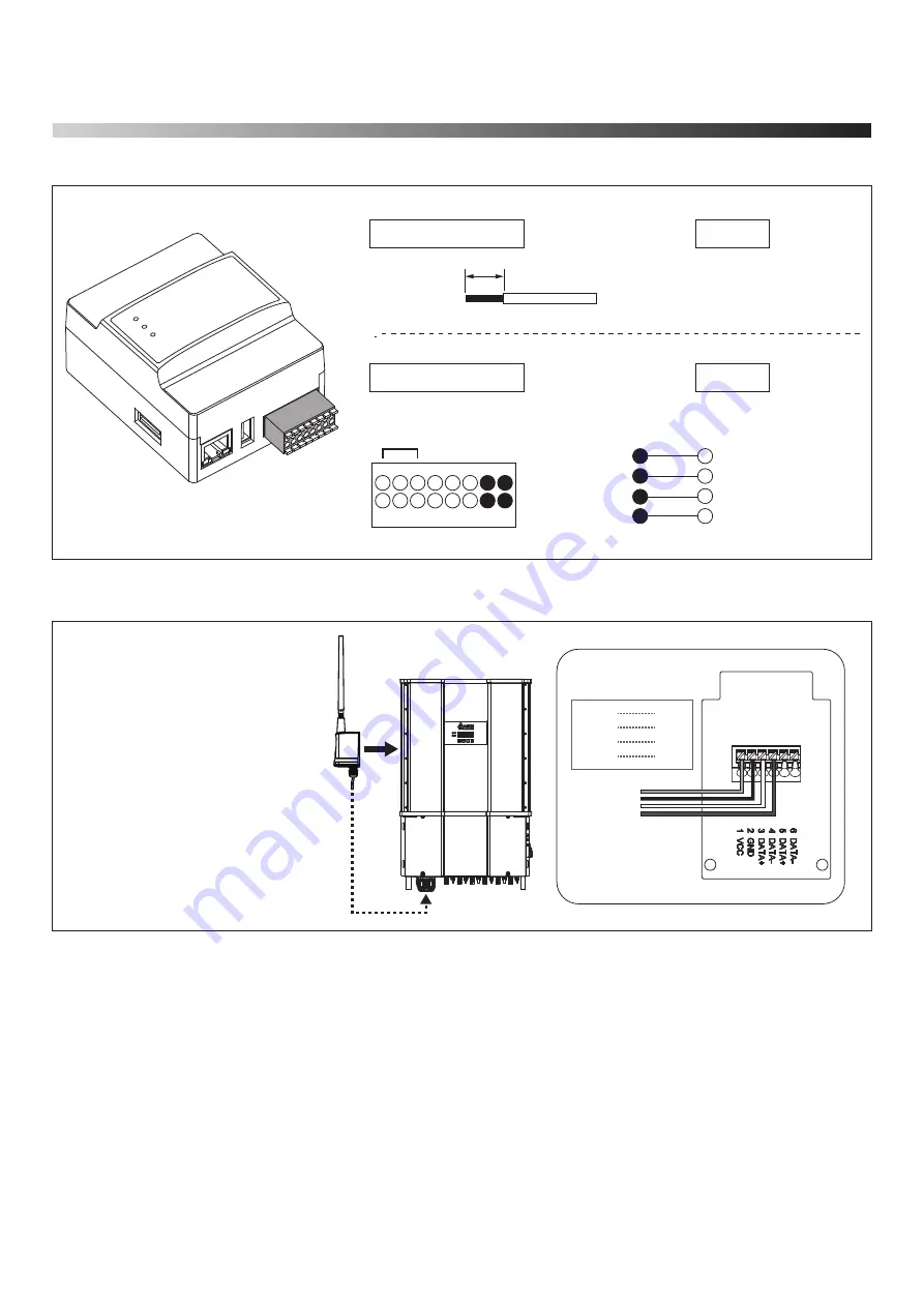
2.4.Connection to the inverter
8
0.3 ~ 0.5 mm
2
Power
RS485-1
RS485-2
CAN
D
R
Y
DI 1-6
1
2
3
5
7
9
11
13
15
6
8
10
12
14
16
4
Inverter
Shielded twisted-pair cable
CAT5 / CAT6
DC1 Data collector
RS-485
1
2
3
4
RS485 - DATA–
RS485 - DATA+
RS485 - GND
RS485 - 12/24 V
See manual of the inverter
Power - GND
Power - +
RS485-1 - B
RS485-1 - A
Inverter
DC1 Data collector
N2
SUB_1G
Inverter
comm. module
Red
Black
White
Green
VCC
GND
D+
D-
■ Install SUB_1G to inverter.
■
Refer the figure and connect each wire
to the communication card of inverter.
* Screw torque required for
assembling: 1.6 N.m
13


