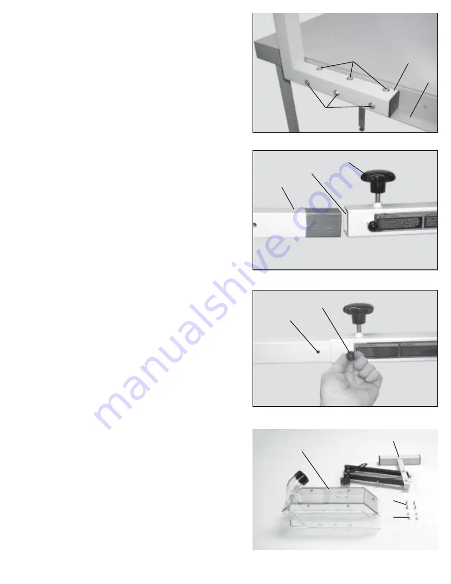
Fig. 15
Fig. 16
Fig. 17
Fig. 18
7
14. Fasten the mounting bracket (A) Fig. 15, to the back
rail (B) using the three 2-3/4” long hex head screws (F),
three 3-3/4” long hex head screws (G), twelve 1/4” flat
washers and six 1/4-20 hex nuts. Place one flat washer
on each hex head screw before inserting through the guard
mount bracket. Then place the remaining washers on the
hex head screws and secure with the six 1/4-20 hex nuts.
15. Thread knob (H) Fig. 16, into mounting bracket (A) as
shown. Insert T-arm (J) Fig. 16, into mounting bracket (A).
16. Pull stop pin (K) Fig. 17, to allow the T-Arm to slide
past stop pin indexing hole (L).
17. Assemble basket body assembly (M) Fig. 18, to blade
guard basket assembly (N) using the four (4) #10-32 x
5/8” flat head screws (P) and four (4) #10-32 locknuts (Q).
Do not completely tighten screws at this time.
A
B
F
G
H
A
J
K
L
M
N
P
Q


