background image

12

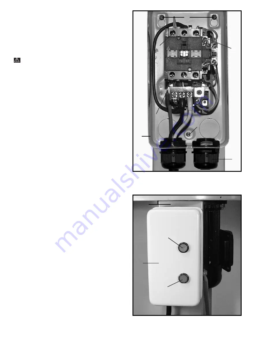
Fig. 32

CONNECTING MACHINE
TO POWER SOURCE

MODEL 50-866 
SINGLE PHASE
INSTALLATION

WARNING: Installation by a qualified electrician is

recommended to assure safe and proper wiring and
product operation.

The motor rating for your single phase dust collector is
230 Volts, 5 H.P. Before connecting your dust collector
to an electrical power system, be sure the electrical
system agrees with the motor rating of the tool.

The single phase Model 50-866 Dust Collector is
supplied with a motor and controller; however, it is not
furnished with a power cord or plug. To connect the dust
collector to a power system, proceed as follows:

1.

Assemble the control box (A) Fig. 32, to the front of

the side support (H) Fig. 33. Insert sheet metal screws
(B) Fig. 32, through holes in the controller box and
thread the sheet metal screw into the side support and
tighten securely.

2.

Bring the power cord (not supplied) up through the

large knockout hole (C) Fig. 32, in the control box (A) and
connect the two power lines to terminals (D) and the
green ground wire to ground screw (E). 

NOTE: THE

POWER CORD MUST BE INSERTED THROUGH THE
BUSHING IN THE ACCESS HOLE (C), TIGHTEN THE
ACCESS HOLE NUT OVER THE ACCESS HOLE TO
HOLD THE POWER CORD IN PLACE.

3.

Reassemble the cover onto the controller box (A)

Fig. 33.

4.

The ON/OFF buttons are located at the front of the

control box. To start the machine, push “ON” button (F)
Fig. 33. To stop the machine, push the “OFF” button (G).

Fig. 33

A

F

G

H

B

B

C

A

E

D

D

Summary of Contents for 50-861

Page 1: ...861 Three Phase PART NO 902110 04 18 02 Copyright 2002 Delta Machinery To learn more about DELTA MACHINERY visit our website at www deltamachinery com For Parts Service Warranty or other Assistance p...

Page 2: ...with padlocks master switches or by removing starter keys 9 DON T FORCE TOOL It will do the job better and be safer at the rate for which it was designed 10 USE RIGHT TOOL Don t force tool or attachme...

Page 3: ...the top of the power cord 9 DO NOT unplug the dust collector by pulling on the power cord ALWAYS grasp the plug not the cord 10 DO NOT handle the plug or dust collector with wet hands 11 REPLACE a da...

Page 4: ...Hardware for Mounting Side Supports Includes 5 16 18 x 5 8 Hex Head Screws 4 and 5 16 Lockwashers 4 4 Cross Member Supports 2 5 Hardware for Mounting Cross Members Includes 5 16 18 x 5 8 Hex Head Scre...

Page 5: ...lower Assembly Includes 5 16 18 x 5 8 Hex Head Screws and 5 16 Lockwashers 16 ea 6 Dust Intake Port 7 Sheet metal Screws 4 8 Dust Intake Port Caps 4 1 Filter Bag Supports 2 2 Filter Bags 12 3 Upper Ba...

Page 6: ...5 16 lockwasher C on a 5 16 18 x 5 8 hex head screw D and insert the screw through the side support and thread the screw into the base Repeat this process for the remaining screw Attach the other sid...

Page 7: ...rted through the side support place a 5 16 lockwasher onto the stud thread a 5 16 18 hex nut onto the stud and tighten securely Repeat this process for the three remaining studs 6 Fig 11 illustrates t...

Page 8: ...this process for the remaining hole Assemble the remaining three drum support posts to the base in the same manner 2 Assemble the top of drum support post A Fig 17 to drum D Place a 5 16 flat washer o...

Page 9: ...S OR ANY FOREIGN MATTER INTO THE DUST INTAKE PORTS ASSEMBLING BAG SUPPORTS BAG HANGERS AND FILTER BAGS TO DRUMS 1 Assemble bottom half of threaded lower bag support A Fig 21 to center of drum assembly...

Page 10: ...r bag support H making certain the pin F in lower bag support engages hole in upper bag support Assemble the remaining bag support in the same manner 5 Position top of filter bags J Fig 24 onto both h...

Page 11: ...or NOTE Make certain locking band F Fig 29 is positioned in the channel of drum C before fastening clamp A 2 Place the opening of the dust bag B Fig 28 over the bottom lip of drum C as shown Fig 30 MO...

Page 12: ...ows 1 Assemble the control box A Fig 32 to the front of the side support H Fig 33 Insert sheet metal screws B Fig 32 through holes in the controller box and thread the sheet metal screw into the side...

Page 13: ...The fan should rotate in a clockwise direction CAUTION DO NOT INSERT FINGERS OR ANY FOREIGN OBJECT INTO THE DUST INTAKE PORT Rotation of the motor can be reversed by interchanging any two of the three...

Page 14: ...st and dirt Blow off motor with low pressure air to remove dust or dirt Air pressure above 50 P S I should not be used as high pressure may damage insulation and blow dirt under loosened tape The oper...

Page 15: ...will repair or replace at its expense and at its option any Delta machine machine part or machine accessory which in normal use has proven to be defective in workmanship or material provided that the...

Page 16: ...90 5555 Fax 909 390 5554 San Leandro 94577 Oakland 3039 Teagarden Street Phone 510 357 9762 Fax 510 357 7939 COLORADO Arvada 80003 Denver 8175 Sheridan Blvd Unit S Phone 303 487 1809 Fax 303 487 1868...

Reviews: