14 -
English
MACHINE USE
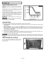
RECOMMENDED DEPTH OF CUT
NOTE: One revolution of the cutterhead adjusting
1/16"
(1.6 mm)
3/32"
(2.4 mm)
1/8"
(3.2 mm)
2"
(51 mm)
4"
(102 mm)
SOFT WOOD
HARD WOOD
RECOMMENDED DEPTH OF CUT
Fig. 23
6"
(152 mm)
7"
(178 mm)
8"
203 mm)
9"
229 mm)
10"
(254 mm)
WIDTH OF STOCK
handle will move the cutterhead up or down 1/16"
(1.6 mm).
You can make an 1/8" (3.2 mm) depth of cut in soft
woods up to 6" wide and in hard woods up to 4"
(102 mm) wide. (See Fig. 23).
For 10" (254 mm), 12" (305 mm), and 13" (330 mm)
wide soft wood, use a maximum depth-of-cut of 1/16"
(1.6 mm). For 10" (254 mm), 12" (305 mm), and 13"
(330 mm) wide hard wood, use a maximum depth-of-cut
of 3/64" (1.2 mm) (Fig. 23).
IMPORTANT: A shallow depth-of-cut will produce a
better finish.
Continuous operation at more than 3/64"
(1.2 mm) can cause motor damage.
OPERATING HINTS
When using your machine, follow these few simple steps to achieve the best results.
1. True Up One Face – Feed one face of the board through a jointer. Make thin cuts with each pass until the entire
surface is flat.
2. Plane to Thickness – Place the surfaced side (STEP 1) face down and feed the board through a planer until
the opposite side is flat. Plane both sides of the board until you achieve your desired thickness. Make thin cuts,
alternating sides with each pass. If, during the planing operation, you notice the board twisting, warping or
bowing, start again with STEP 1.
3. Support both ends of the long workpieces.
4. For best results, engage the cutterhead lock before planing. Plane with the grain only. Keep the planer table clean.
Occasionally, wax the table surface to reduce friction during the planing operation.
5. Cross-cut your lumber to the final length.
The knives on the planer will not wear evenly if the wood is fed through the same spot on the table every
time. Feed the wood through the planer at different spots on the table when possible to help eliminate uneven wear of
the knives.
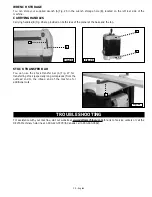
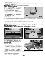
KNIFE TRANSFER TOOL STORAGE
You can store your supplied knife transfer tool (A)
Fig. 24
B
A
Fig. 24 underneath the outfeed table extension (B) on
the Velcro strip.

