Modulon NH Plus Series
5-4
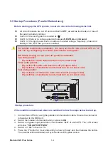
5-5 Startup Procedures (Parallel Redundancy)
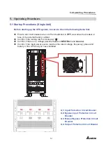
Before starting up the UPS system, be sure to check the following items first.
All circuit breakers are cut off and switched to
OFF
, as well as the breaker or fuse of
the external battery cabinet.
Confirm if the locking latch is located at
“
±
”
.
Confirm if there is no voltage potential between
NEUTRAL
and
Ground
.
Confirm if the input power source matches the rated voltage, frequency, phase and
battery of the UPS that you have installed.
Startup procedure:
If the conditions mentioned above are satisfied, follow the steps below to start up.
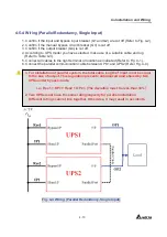
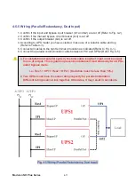
1. Connect two UPSs by using the parallel communication cable. Ensure the connector
is fastened to the DB9 port.
2. Switch the breaker of external battery cabinet to
ON
.
3. Switch on bypass input protection circuit breaker
“Q2”
of each UPS. The LCD screen
will show
”ON AUTO BYPASS”
.
4. Switch
on
“Q1”
of each UPS.
5. Press
the
“
I
” button for 3 seconds until you hear a “beep” and then release the button.
The inverter will be activated and synchronize with bypass source.
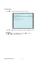
For parallel redundancy installation, you must set the ID code of each UPS as “01”
and “02” by configuring the control panel. Refer to Chapter 7.
DIP Switch Setting on rear panel for parallel installation:
Two units parallel:
Dip switches of two units must turn on (on lower side).
Three units parallel:
Dip switch of middle unit must turn off (on upper side).
Dip switches of another two units must turn on (on lower side).
Four units parallel:
Dip switches of middle two units must turn off (on upper side).
Dip switches of another two units must turn on (on lower side).
P1
P2
P3
P4
P5
P6
P7
RS232
OUTPUT DRY CONTACT
PARALLEL
PARALLEL

