background image


6) 

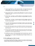
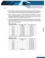
ed for the trim-down or trim-up setting of the Output Voltage. For IPM, if the 

converter requires a trim up, set SW3 to the Trim-up position. If the converter requires a 


7) 

resistors. For IPM12C0A0R04A, if the converter requires a trim-up to 5V, set the SW4_1

 
8) 

rim-up, set the SW4_2 to 

ON position and SW3 to trim-up position. If the converter requires a trim-down, set the 


Subdivide switch NO. 

For adjustable output 

module 

For constant output 

module 

trim down, set SW3 to the Trim-down position. For normal operating, turn off the SW3.   

SW4 and SW5 are used for the Output Voltage Set-Point Adjustment by externa

to ON position and SW3 to trim-up position. If the converter requires a trim-down to 0.8V, 
set the SW5_8 to ON position and SW3 to trim-down position.   

For constant output voltage module, if the converter requires a t

SW5_8 to ON position and SW3 to trim-down position. Please refer to the Function 
Tables below for the setting details. 

SW4 Function Table 

SW4_1 

5.0V setting 

5.0V trim up 

SW4_2 

3.3V setting


3.3V trim up


SW4_3 

2.5V setting


2.5V trim up


SW4_4 

1.8V setting


1.8V trim up


SW4_5 

1.5V setting


1.5V trim up


SW4_6 

1.2V setting


1.2V trim up


SW4_7 1.0V 

setting


1.0V trim up


SW4_8 

0.95V setting 

0.9V trim up


  Note: Settings of SW4_1 and SW4_7 are for IPM12C se


Subdivide switch NO. 

For adjustable output 

module 

For constant output 

module 

ries only 

SW5 Function Table 

SW5_1 

5.0V trim down 

SW5_2 

3.3V trim down


SW5_3 

2.5V trim down


SW5_4 

1.8V trim down


SW5_5 

1.5V trim down


SW5_6 

1.2V trim down


SW5_7 

1.0V trim down


SW5_8 

0.80V setting 

0.9V trim down


SW3 is us

Summary of Contents for DEP-003

Page 1: ...ering from a world leader in power systems technology and manufacturing Delta Electronics Inc They operate from a 3V 5 5V IPM04C or an 8V 14V IPM12C source and provide a programmable output voltage of 0 8V to 3 3V IPM04C or 0 8V to 5V IPM12C With creative design technology and optimization of component placement these converters possess outstanding electrical and thermal performance as well as off...

Page 2: ...ltimeters one with 20A range and ideally all with 4 1 2 digit resolution DVM1 DVM2 and DVM3 Zentech 2041 or equivalent Electronic load Chroma 63030 or equivalent 300W approx rating or a suitable resistive load DC power supply GW GPC 3060D or equivalent 4 0 Equipment Set Up and Description Please refer to the Power Module Evaluation Board Layout see page 15 for reference designators cited in this d...

Page 3: ...measure the input current Evaluation Board Note Use stranded leads at least equivalent to 14 AWG for all connections in sections 4 1 and 4 2 and SVin Pins on the Evaluation Board This multimeter is designated DMM2 to measure the input voltage and SVout Pin on the Evaluation Board The multimeter is designated DMM3 DMM3 is used to measure the output voltage to Channel 1 of the oscilloscope item 3 2 ...

Page 4: ...r and turn SW1 to the ON position to disable the converter 5 position if this nction is not being used Turn SW2 to the ON position if the Transient function test is The following tests are Input Characteristics Under Voltage Locko No Load Input Current utput Characteristics Load Regulation Output Regulation Output Voltage Se ynamic Characteristics Turn on Response time Thermal Characteristic 7 0 T...

Page 5: ...down to 0 8V set the SW5_8 to ON position and SW3 to trim down position For constant output voltage module if the converter requires a t SW5_8 to ON position and SW3 to trim down position Please refer to the Function Tables below for the setting details SW4 Function Table SW4_1 5 0V setting 5 0V trim up SW4_2 3 3V setting 3 3V trim up SW4_3 2 5V setting 2 5V trim up SW4_4 1 8V setting 1 8V trim up...

Page 6: ...he nominal output voltage Set the switch SW1 to the ON position after performing each test 8 1 Input Characteristics 8 1 1 Input Voltage Ra The IPM04C Series of DC DC converters will operate at full loa th DC DC converters will operate at full load from 8Vin to 14Vin for 12Vin nominal types The converters feature input under voltage protection which will not allow the converter to start up unless ...

Page 7: ...nge the operating ion Output Ripple is defined as the periodic AC component on the DC DC converter s output le is measured in terms of peak to peak and RMS values both done ith a specific bandwidth Set the switch SW1 to the OFF position to enable the converter just the input voltage while monitoring DMM2 and set the output load to the full rated nd 10mV Div using the 5 ple of the DC DC converter i...

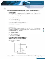
Page 8: ...ic 1 Output Voltage Set Point Adjustment by using an external resistor For IPM12C se To implement Trim up by using an external resistor Rtrim up must be connected Vout The value of R also be referred for further information Ω k V R up trim 261 0 9 0 752 3 out To implement Trim down by using an external resistor Rtrim down must be connected between the TRIM pin and Vout For IPM12C0A0R04A Please ref...

Page 9: ... to the IPMR table for the desired R th Vout The value of Rtrim down can be calculated by the following equation and the datasheet can also be referred for further information Ω k out V down trim 187 10 9 0 0 2 IPMR Rtrim values versus some commonly used Vout for IPM04C0A0R06A R Vout Rtrim Ω 0 8 9 813K 0 9 Open 1 2 23 146K 1 5 11 479K 1 8 7 590K 2 5 4 188K 3 3 2 729K Test 1 Turn on the fan just th...

Page 10: ...e of a IPM module to 3 3 Vdc Vtrim is calculated as follows Vtrim 0 7439 0 0488 x 3 3 0 5829V For IPM04C series Output voltage of IPM04C is programmable while applying a voltage between the TRIM and GND pins The following equation can be used to determine the value of Vtrim needed for a desired output voltage Vo Vtrim 0 7168 0 0187Vo Vtrim is the external voltage in V Vo is the desired output volt...

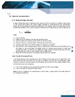
Page 11: ...he oscilloscope to be AC coupled and to 50mV Div and for 50uS Div Set the trigger to auto and adjust the trigger point at a negative going pulse for step load change from 50 to 100 of Io or adjust the trigger point at positive going pulse for step load change from 100 to 50 Please refer to data sheet 7 Measure the Peak deviation and capture the waveform as required 8 3 2 Turn On Transient Time Tur...

Page 12: ...oscope to be DC coupled and to 1V division Refer to data sheet 4 Connect a scope probe from channel 1 between the on off control pin and reference ground SGND on the Evaluation Board 5 Set channel 2 on the oscilloscope to be DC coupled and to the appropriate range for the output voltage 6 Connect a coaxial cable from channel 2 to BNC2 on the Evaluation Board 7 Set the Time base to 5mS Div 8 Set th...

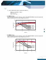
Page 13: ...R04A converter measured at different operating points the output voltage was set at 5V 70 80 90 100 1 2 3 LOAD A EFFICIENCY 4 Vi 14V Vi 12V Vi 10V Vi 8V For IPM04C series The following graph shows the efficiency results of the IPM04C0A0R06A converter measured at different operating points the output voltage was set at 3 3V 75 85 95 1 2 3 4 5 6 LOAD A EFFICIENCY Vin 5 5V Vin 5 0V Vin 4 0V 13 ...

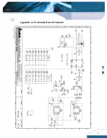
Page 14: ...14 Appendix A Evaluation Board Schematic ...

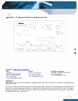
Page 15: ...15 Appendix B Evaluation Board Layout Top View ...

Page 16: ...WARRANTY Delta offers a two 2 year limited warranty Complete warranty information is listed on our web site or is available upon request from Delta Information furnished by Delta is believed to be accurate and reliable However no responsibility is assumed by Delta for its use nor for any infringements of patents or other rights of third parties which may result from its use No license is granted b...

Reviews: