background image

1. 


IMPORTANT SAFETY INSTRUCTIONS 


z

  This manual contains important instructions that should be followed during installation and 

maintenance of the UPS and batteries. 

z

  Install the on line UPS in a well ventilated area, away from flammable liquids and gases. Do 

not let the unit come in contact with water.   

z

  External slits and openings in the cabinet are provided for ventilation. To ensure reliable 

operation of the product and to protect from overheating these openings must not be 

blocked or covered. Objects must never be inserted into ventilation holes or openings. 

z

  Do not stand beverage containers on the unit. 

z

  This UPS was designed to power all modern computer loads and associated peripheral 

devices, such as monitors, modems, cartidge tape drives, external floppy drives etc.. Do not 

use it for pure inductive or capacitive loads. It is not rated to power life support equipment. 

z

  All recorded media, such as diskettes, tapes and cartridges, should be kept a minimum of 

60cm from the UPS. Otherwise, the magnetic field created by operation of the UPS may 

erase data on those devices. 

z

  All repairs or installation should be performed by qualified service personnel. The UPS 

contains voltages which are potentially hazardous. The output receptacles may be alive 

even when the UPS is not connected to the mains. 

z

  Risk of a possible electrocution is possible when the battery is connected to the UPS. 

Therefore, do not forget to disconnect the batteries before any service is to be done on the 

UPS. To disconnect, remove the battery fuse holder which is located at the rear panel of the 

UPS. 

z

  Isolate Uninterruptible Power Supply (UPS) before working on the circuit. A readily 

accessible disconnect device shall be incorporated in the fixed wiring. 

z

  HIGH LEAKAGE CURRENT – Earth connection essential before connecting power source. 

z

  Federal Communications Commission Interference Statement 

This equipment has been tested and found to comply with the limits for a Class A digital 

device, pursuant to Part 15 of the FCC Rules. These limits are designed to provide 

reasonable protection against harmful interference when the equipment is operated in a 

commercial environment. This equipment generates, uses and can radiate radio frequency 

energy and, if not installed and used in accordance with the instructions manual, may 

cause harmful interference to radio communications. Operation of this equipment in a 

residential area is likely to cause harmful interference in which case the user will be 

required to correct the interference at his own expense. 

FCC Caution: To assure continued compliance, (example-use only shielded interface 

cables when connecting to computer or peripheral devices). Any changes or modifications 

not expressly approved by the party responsible for compliance could void the user’s 

authority to operate this equipment.   

Summary of Contents for Amplon Family

Page 1: ...www deltapowersolutions com Delta UPS Amplon Family User Manual The power behind competitiveness N Series Single Phase 6 12 kVA...

Page 2: ...Any disposition duplication dissemination reproduction modi cation translation extraction or usage of this Manual in whole or in part is prohibited without the prior written permission of Delta Given...

Page 3: ...4 4 HANDLING 13 5 OPERATION 14 5 1 POWER ON OFF INVERTER 14 5 2 LCD FUNCTION SELECTION SWITCH 16 5 3 PARAMETER SET UP MODE 17 5 4 OPERATION ON BYPASS VOLTAGE BEYOND ALLOWABLE RANGE 19 5 5 OVERLOAD AND...

Page 4: ...k of a possible electrocution is possible when the battery is connected to the UPS Therefore do not forget to disconnect the batteries before any service is to be done on the UPS To disconnect remove...

Page 5: ...isk of electric shock and chemical hazard The following precaution should be observed when working on batteries Remove watches rings or other metal objects Use only tools with insulated handles The co...

Page 6: ...provide detailed information on operation status z Manual and static bypass switch forms Allowance for switching to the main power supply z Static bypass supply circuit incorporates functions such as...

Page 7: ...ON LINE and ECONOMY modes pressing the up button for more than 3 seconds can detect the battery capacity NOTE If the UPS is in alarm status pressing the up or down button for more than 3 seconds can d...

Page 8: ...5 2 3 REAR CONTROL PANEL 6KVA 11 10 6 1 4 2 5 8 7 9 3 EMERGENCY 240VDC 20A AC BREAKER INPUT MANUAL BYPASS POWER OFF CONTACT DRY RS 232 SNMP BATT NO...

Page 9: ...6 12KVA MANUAL BYPASS 240VDC 40A RS 232 CONTACT EMERGENCY DRY POWER OFF SNMP BATT NO 11 9 8 7 4 1 6 10 5 3 2...

Page 10: ...onnects to external battery cabinet to extend the backup time 5 AC INPUT BREAKER Provides safe protection for UPS AC input 6 EXHAUST FANS For cooling air ventilation of UPS 7 REMOTE EMERGENCY POWER OF...

Page 11: ...5 Hz Programmable 3 5 Input Protection Circuit Breaker 40A 1 pole x 1 63A 1 pole x 1 4 Output 4 1 Output Voltage RMS Voltage 120V 220Vac single phase Static Regulation r 2 4 2 Harmonic Distortion 5 4...

Page 12: ...4200W 3 Minutes 8400W 6 Operation 6 1 Transfer Time On line Mode Main Power Failure 0ms Main Power Recover 0ms Inverter To Bypass 1ms Bypass To Inverter 1ms Economy Mode Main Power Recover 0ms Inverte...

Page 13: ...G 365 7LB Battery Cabinet Weight 180KG 396LB 12 Environment 12 1 Ambient Operating Temperature 0o C 40 o C 32 o F 104 o F 12 2 Ambient Storage Temperature 20 o C 40 o C 4 o F 104 o F 12 3 Relitive Hum...

Page 14: ...s 20qC to 60qC without batteries 20qC to 45qC with batteries for a short period Maximum period for battery storage 6 months at 20qC or 3 months at 30qC Eight hours of charging time is needed when the...

Page 15: ...the wiring with suggested suitable conduit and bushing as below z Conduit Flexible metal conduit sized one inch z Bushing Overall diameter is 40 5mm height is 13 1mm Input and Output Connection When c...

Page 16: ...er to Fig 1 2 or Fig 1 3 z The UPS should always have a clearance space of 300mm at the rear and 100mm on its side Refer to Fig 4 Fig 1 Fig 2 Fig 3 Fig 4 First change the direction and revolve screw p...

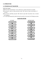
Page 17: ...UPS starts diagnostic test and shows the results on the back lit LCD display as below DIAGNOSIS MODE AC START BATTERY START DIAGNOSIS MODE FREQ OUT XXHZ DIAGNOSIS MODE INPUT XXXV XXHZ DIAGNOSIS MODE R...

Page 18: ...hed to BYPASS mode z If the UPS is in backup mode the message UPS OFF WAITING will be displayed on LCD about thirty seconds then disappear z Before removing the battery connect wire please wait until...

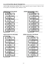
Page 19: ...T KEY PRESS THE SELECT KEY CHRG XXXV FLOAT BOOST PRESS THE SELECT KEY PRESS THE SELECT KEY IN XXXV XX XHz ECONOMY MODE ECONOMY MODE ECONOMY MODE ECONOMY MODE ECONOMY MODE ECONOMY MODE OPERATION IN ON...

Page 20: ...e t i n i t i a l S e l e c t e c o n o m y m o d e R e t u r n t o s e t i n i t i a l S e l e c t o u t p u t f r e q u e n c y R e t u r n t o s e t i n i t i a l UPS SET UP EXIT ENTER OUTPUT VOLTA...

Page 21: ...5Ah 16 090Ah 21 140Ah 26 190Ah EXTEND NONE SCROLL SELECT EXTEND BATTERY SCROLL SELECT EXTEND 010Ah SCROLL SELECT EXTEND 015Ah SCROLL SELECT EXTEND 190Ah SCROLL SELECT EXTEND 200Ah SCROLL SELECT TO UPS...

Page 22: ...XXX X XXKW 1 minute 125 150 OVERLOAD 125 LOAD XXX X XXKW 30 seconds 150 OVERLOAD 150 LOAD XXX X XXKW Immediate Shutdown Operation Condition LCD Display Message Extended Overload OVERLOAD XXX SHUT DOWN...

Page 23: ...the AC input power is directly supplied to the load CAUTION Activate manual bypass switch only when the UPS is in BYPASS mode BYPASS BYPASS NORMAL NORMAL z STEP 1 Turn off the inverter power to switc...

Page 24: ...pin 2 5 or pin 4 5 or pin 4 3 then the UPS will be powered off NOTE This port must not be connected to the Telecom Port z Load level z Battery status z Battery level z UPS mode z Input voltage z Outp...

Page 25: ...ry contact table Pin State Pin 8 3 Pin 1 3 Pin 6 3 Pin 5 3 Pin 2 3 Normal Open Open Open Back up Close Low Battery Close Fault Close Bypass Close Open Inverter Open Close Pin Assignment Fig 5 2 NOTE m...

Page 26: ...MP network interface is a powerful tool for remote control and UPS monitoring NOTE For more information on SNMP card optional contact your local dealer MANUAL BYPASS 240 VDC40A RS 232 CONTACT EMERGENC...

Page 27: ...PACK When the UPS is connected with Delta s standard battery packs you can detect the total battery capacity by linking the UPS to the battery pack NOTE This function can detect up to a maximum of tw...

Page 28: ...ce or irresistible force i e war re natural disaster etc and this warranty also expressly excludes all inci dental and consequential damages Maintenance service for a fee is provided for any damage ou...

Page 29: ......

Page 30: ......

Page 31: ......

Page 32: ......

Reviews: