


21
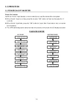
6. COMMUNICATION INTERFACE
6-1 RS232 INTERFACE
A 9-pin female SUB-D connector is provided on rear panel of UPS to transmit the UPS
signals to the computer. Using the Delta “UPSenrty Smart 2000” software allows users to
check the power status. The details on signals are shown as below.
6-2
REMOTE EMERGENCY POWER OFF (REPO)
Pin Assignment of RJ11:
If short pin (2, 3) or pin (2, 5) or pin (4, 5) or pin (4, 3), then the UPS will be powered off.
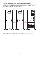
NOTE:
This port must not be connected to the Telecom Port.
z
Load level
z
Battery status
z
Battery level
z
UPS mode
z
Input voltage
z
Output voltage
z
Input frequency
z
Temperature inside unit
z
Set shut-down delay time
z
Enable / Disable beeper
z
Remote shut-down
2
1
3
4
5
6
1
2
3
4
5
6
X
X
12V
Pin Assignment:
z
Pin 2: TXD (Transmit Data)
z
Pin 3: RXD (Receiving Data)
z
Pin 5: GND (Signal Ground)
z
Pin 7: PNP (Signal Receiving)
Hardware:
z
Baud Rate ----------------2400 bps
z
Data Length -------------- 8 bits
z
Stop Bit ------------------ 1 bit
z
Parity --------------------- NONE


